Design method of full-dynamic mobile robot chassis with self-adaptive adjustment function

A mobile robot and self-adaptive adjustment technology, applied in the direction of motor vehicles, elastic suspensions, suspensions, etc., can solve the problems of not being able to turn quickly, slow moving speed, high price, etc., to improve the ability to overcome obstacles, ensure stability, The effect of improving reliability

Inactive Publication Date: 2021-06-04
苏州需要智能技术有限公司
View PDF0 Cites 0 Cited by
  • Summary
  • Abstract
  • Description
  • Claims
  • Application Information

AI Technical Summary

Problems solved by technology

[0002] At present, with the development of science and technology, there are more and more applications of robots. The overall moving speed of existing mobile robots is relatively slow. The main reason is that the outdoor environment is relatively complicated. It is necessary to reduce its own speed, and then increase the speed after the robot completes the turn or crosses obstacles, so that the mobile robot cannot maintain high-speed operation
[0003] The existing general-purpose adaptive robot chassis design method has certain disadvantages. First, the rigidity of the robot chassis cannot be adjusted, and it cannot turn quickly on flat roads, and at the same time, the vibration is relatively large on rough roads. The actual situation adjusts the height of the chassis to overcome obstacles. Also, it cannot be adjusted adaptively according to different road conditions. Finally, the air suspension in the automotive field is not compact enough, heavy, and relatively expensive; for this reason, we A design method for the chassis of a fully dynamic mobile robot with adaptive adjustment function is proposed

Method used


Image

  • Design method of full-dynamic mobile robot chassis with self-adaptive adjustment function
  • Design method of full-dynamic mobile robot chassis with self-adaptive adjustment function
  • Design method of full-dynamic mobile robot chassis with self-adaptive adjustment function

Examples


Embodiment Construction

[0041] Next, the technical solutions in the embodiments of the present invention will be apparent from the embodiment of the present invention, and it is clearly described, and it is understood that the described embodiments are merely embodiments of the present invention, not all of the embodiments. Based on the embodiments of the present invention, there are all other embodiments obtained without making creative labor without making creative labor premises.

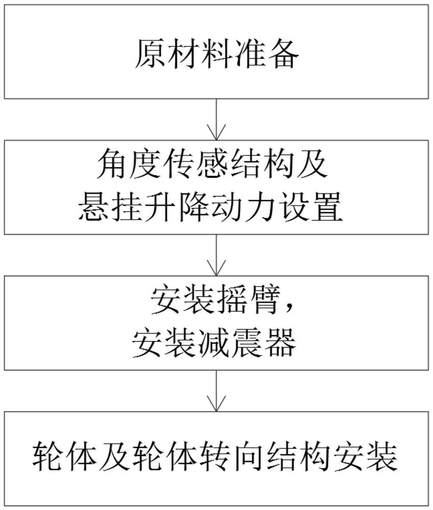
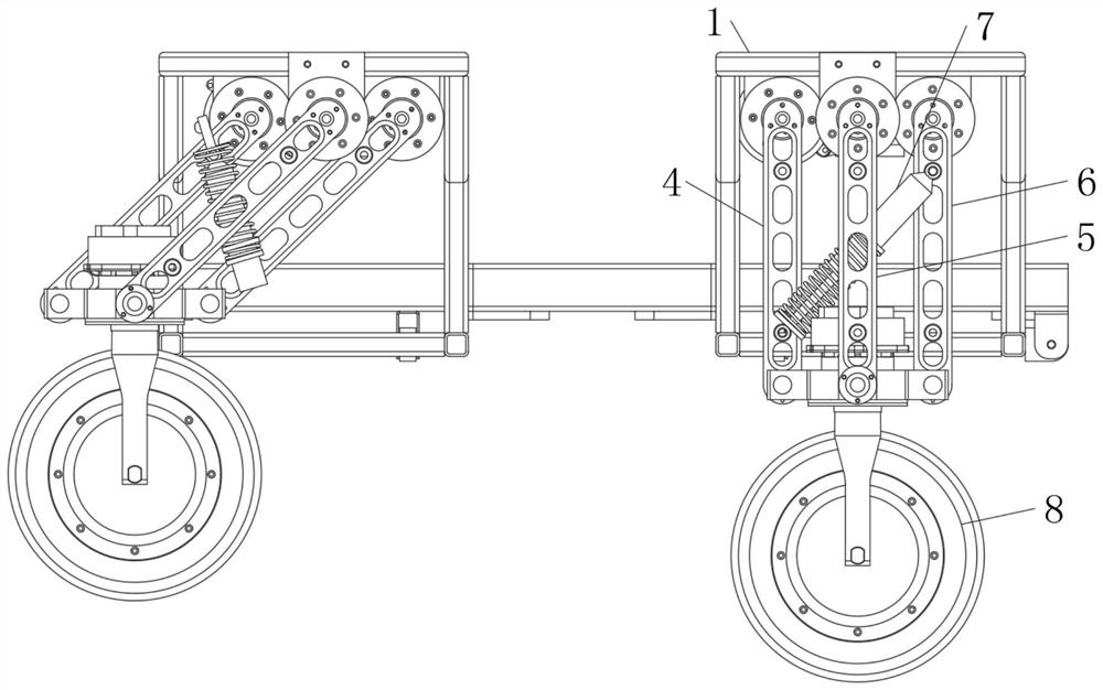
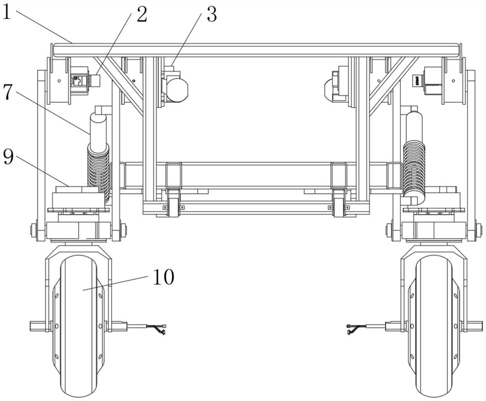
[0042] See Figure 1-5 Fully dynamic mobile robot chassis design method with adaptive adjustment function, including raw material preparation - angle sensing structure and suspension lifting power setting - mounting rocker arm, mounting shock absorber 7-wheel body and wheel steering structure mounting design steps, Specific steps are as follows:

[0043] (1) Raw material Preparation: A certain amount of frame body 1, angle sensor 2, suspended lift motor 3, rocker arm, shock absorber 7, tire, hub motor 10 and tire steering mo...


PUM


Abstract

The invention relates to the technical field of robot design, and discloses a full-dynamic mobile robot chassis design method with a self-adaptive adjustment function. The method comprises the steps: raw material preparation, angle sensing structure and suspension lifting power arrangement, rocker arm installation, damper installation and wheel body and wheel body steering structure installation and design. The method comprises the following specific steps: (1) preparing raw materials, wherein a certain amount of frame bodies, angle sensors, suspension lifting motors, rocker arms, shock absorbers, tires, hub motors and tire steering motors are prepared. According to the universal self-adaptive robot chassis design method, the rigidity of the robot chassis is adjustable; meanwhile, the height of the chassis is adjustable, self-adaptive adjustment can be conducted according to different road conditions, and the chassis can automatically and intelligently adapt to various road conditions; and the suspension structure has the characteristics of being compact, light in weight and relatively low in price, is more suitable for the field of mobile robots, and can bring better use prospects in practical application.

Description

Technical field [0001] The present invention relates to the field of robotic design techniques, specifically a full-dynamic mobile robot chassis design method with adaptive adjustment function. Background technique [0002] At present, with the development of science and technology, there are more and more robots, and the overall movement speed of existing mobile robots is slower. The main reason is that the outdoor environment is more complicated, when the mobile robot needs to turn or get it, It is necessary to reduce its own speed, and then increase the speed after the robot is turned or over the obstacle, so that the mobile robot cannot operate at a high speed. [0003] The existing general adaptive robot chassis design method has some drawbacks. First, the rigid chassis stiffness is not adjustable. In the flat road, it is not able to turn quickly, and the vibration of the rugged section is large. Second, the chassis is not adjustable, and cannot be based on The actual situat...

Claims


Application Information

Patent Timeline
Patent Type & Authority Applications(China)
IPC IPC(8): B62D65/12B60G17/019B60G17/015B60R11/04B60R11/00
CPCB60G17/015B60G17/019B60R11/00B60R11/04B62D65/12
Inventor 鲜鳞波彭鹏
Owner 苏州需要智能技术有限公司
Why Eureka
Try Eureka