Bicycle driving mechanism and bicycle

A driving mechanism and bicycle technology, which is applied in rider driving, vehicle components, vehicle gearboxes, etc., and can solve problems such as inability to start, difficulty in coherent exertion by cyclists, and inability of cyclists to exert force

Inactive Publication Date: 2021-06-04
张金星
View PDF0 Cites 0 Cited by
  • Summary
  • Abstract
  • Description
  • Claims
  • Application Information

AI Technical Summary

Problems solved by technology

[0003] This kind of driving mode makes the bicycle have a point of fatigue during riding, that is, when the two cranks are perpendicular to the horizontal direction, the torque of the pedal acting on the center shaft is zero at this time, and it needs to rely on inertia or rely on The rider adjusts the action or uses the friction of the sole to make the pedal drive the crank to make a transition, but during this transition, the rider cannot rely on the pedal to generate force to output power to the bicycle
[0004] For example, when starting a bicycle, it is often necessary to adjust the crank to the horizontal direction before starting, but if the crank is in the vertical direction, the rider cannot exert force and cannot start
In addition, when the pedals are pressed to the point of exhaustion during the climbing process of the bicycle, the speed of the bicycle will drop quickly and even stop. It is an unavoidable problem when the crank is driven in a circular motion

Method used


Image

  • Bicycle driving mechanism and bicycle
  • Bicycle driving mechanism and bicycle
  • Bicycle driving mechanism and bicycle

Examples


Embodiment 1

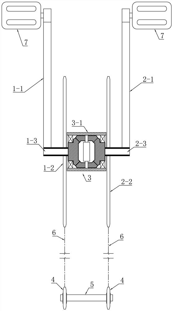
[0055] Such as figure 1 and figure 2 A kind of bicycle driving mechanism shown, it comprises left crank 1-1, left crank sprocket 1-2, left output shaft 1-3, right crank 2-1, right crank sprocket 2-2, right output shaft 2 -3, gear set coupling 3, flywheel 4, rear axle 5, chain 6 and pedal 7.

[0056] Wherein, the gear set coupling 3 is arranged between the left output shaft 1-3 and the right output shaft 2-3, connects the left output shaft 1-3 and the right output shaft 2-3, and makes the left output shaft 1-3 3 and the direction of rotation of the right output shaft 2-3 are opposite.

[0057] see figure 1 and figure 2 , the left output shaft 1-3 and the right output shaft 2-3 are respectively fixedly provided with a left crank sprocket 1-2 and a right crank sprocket 2-2, and the left and right sides of the rear axle 5 are respectively fixedly provided with a flywheel 4 , the left crank sprocket 1-2 and the right crank sprocket 2-2 are respectively connected with the fly...

Embodiment 2

[0067] The difference between the bicycle drive mechanism introduced in this embodiment and Embodiment 1 is that a planetary gear locking mechanism is provided in the gear set coupling 3, and the planetary gear locking mechanism is used to switch only the rotation of the planetary gears. In the state of only revolving, when the planetary gears are rotating and not revolving, the effect of the gear set coupling 3 is the same as that of Embodiment 1, and both the left output shaft 1-3 and the right output shaft 2-3 can be realized through the transmission of the gears. in the opposite state. When the planetary wheel revolves and does not rotate, its left output shaft 1-3 and right output shaft 2-3 turn to the same direction, which is the same as the existing bicycle transmission principle, and the crank is circular.

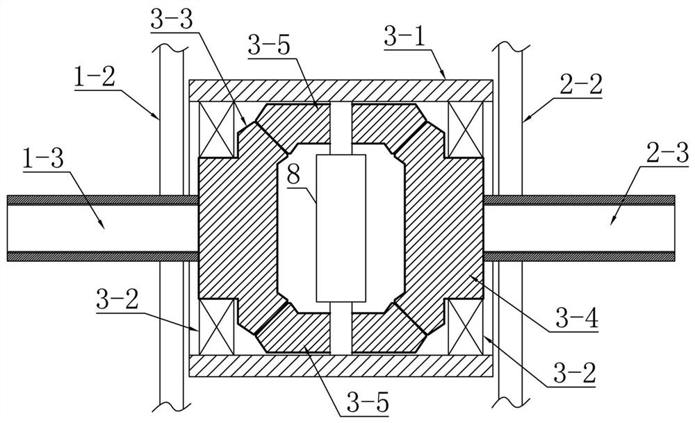
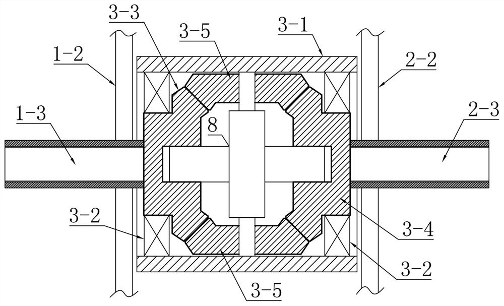
[0068] Specifically, as Figure 5 and 6 As shown, the housing 3-1 of the gear set coupling 3 is provided with a cross-shaped support frame 8, and the support fra...

Embodiment 3

[0079] Such as Figure 13-Figure 15 A kind of bicycle driving mechanism shown, it comprises left crank 1-1, left output shaft 1-3, right crank 2-1, right crank sprocket 2-2, right output shaft 2-3, gear set coupling 3, flywheel 4, rear axle 5, chain 6 and pedal 7. In this embodiment, only the right crank sprocket 2-2 and a flywheel 4 are arranged on the right side, and the right crank sprocket 2-2 is connected with the flywheel 4 through a chain 6.

[0080] The left crank 1-1 is fixedly set on the left output shaft 1-3, the right crank 2-1 is fixedly set on the right output shaft 2-3, and the right crank sprocket 2 is also set on the right output shaft 2-3 -2, pedals 7 are provided at the far ends of the left crank 1-1 and the right crank 2-1.

[0081] Wherein, the gear set coupling 3 is arranged between the left output shaft 1-3 and the right output shaft 2-3, connects the left output shaft 1-3 and the right output shaft 2-3, and makes the left output shaft 1-3 3 and the d...


PUM


Abstract

The invention relates to a bicycle driving mechanism and a bicycle, the driving mechanism comprises a left output shaft, a right output shaft and a gear set coupler, a left crank and a left crank chain wheel are fixedly arranged on the left output shaft, a right crank and a right crank chain wheel are fixedly arranged on the right output shaft, and flywheels are respectively arranged on two sides of a rear axle. The left crank chain wheel and the right crank chain wheel are respectively connected with the flywheels on the corresponding sides through chains; the gear set coupler is connected with the left output shaft and the right output shaft, and enables the rotation directions of the left output shaft and the right output shaft to be opposite. The bicycle uses the driving mechanism. According to the bicycle driving mechanism provided by the invention, the left half shaft and the right half shaft of the middle driving shaft can be in a synchronous reverse rotation state, alternate treading and power generation of left and right feet are realized, cranks are prevented from reaching 'dead points', continuous exertion for riding can be realized, and the treading efficiency is improved.

Description

technical field [0001] The present invention relates to a bicycle driving mechanism and a bicycle including the driving mechanism. Background technique [0002] The driving mechanism of the existing bicycle is to fix two cranks through the two ends of the center shaft, and use a crank sprocket fixed on one of the cranks as the driving sprocket, and drive the driven sprocket of the rear wheel or front wheel through the chain. Drive, wherein the two cranks are set in opposite directions (180 degrees), when one crank is forced to turn downwards, the other crank is passively turned upwards under the action of the central axis, the two cranks alternately exert force, and ride When running, the two cranks do circular motion. [0003] This kind of driving mode makes the bicycle have a point of fatigue during riding, that is, when the two cranks are perpendicular to the horizontal direction, the torque of the pedal acting on the center shaft is zero at this time, and it needs to re...

Claims


Application Information

Patent Timeline
Patent Type & Authority Applications(China)
IPC IPC(8): B62M1/10B62M1/24B62M11/18
CPCB62M1/10B62M1/24B62M11/18
Inventor 张金星
Owner 张金星
Why Eureka
Try Eureka