Pneumatic clamp with rotary suction cup

A technology of pneumatic clamps and rotary suction cups, applied in conveyor control devices, conveyor objects, transportation and packaging, etc., can solve problems such as high defective rate, lack of rotation function, and inability to achieve consistency, and achieve high reliability , fully functional effect

Pending Publication Date: 2021-06-04
XINHUA HUNAN MEDICAL TECH CO LTD
View PDF0 Cites 0 Cited by
  • Summary
  • Abstract
  • Description
  • Claims
  • Application Information

AI Technical Summary

Problems solved by technology

[0002] The existing pneumatic clamps generally only have the function of adsorption, but do not have the function of rotation, which makes it impossible to achieve consistency in subsequent actions, resulting in a high rate of defective products in the production process. Therefore, it is necessary to design a pneumatic clamp with a rotating suction cup. fixture

Method used


Image

  • Pneumatic clamp with rotary suction cup
  • Pneumatic clamp with rotary suction cup
  • Pneumatic clamp with rotary suction cup

Examples


Embodiment 1

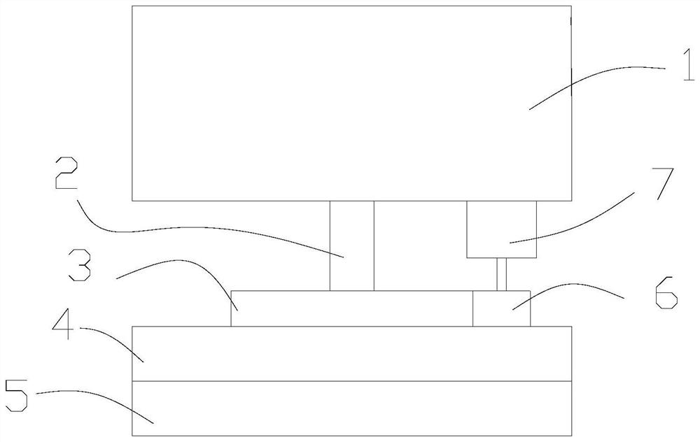
[0021] Embodiment 1: as Figure 1-4 , a pneumatic clamp with a rotating suction cup, comprising a lifting platform 1, a rotating shaft 2, a suction cup mounting plate 4 and a suction cup 5; the lower end of the lifting platform where the rotating shaft is vertically installed, and the suction cup mounting plate is fixed on the lower end of the rotating shaft; the suction cup is installed on the suction cup installation board;

[0022] The lifting platform is provided with a motor 7, and the main shaft of the motor is provided with a driving gear 6; the rotating shaft is also provided with a driven gear 3, and the driven gear meshes with the driving gear.

[0023] The lifting platform is driven by cylinders.

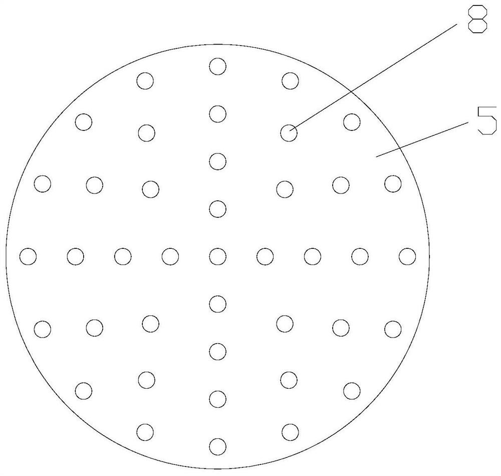
[0024] The suction cup is provided with a plurality of air holes 8, and the air holes communicate with the suction port connected to the air pump.

[0025] The pores are multi-circle, and the multi-circle pores are arranged in concentric circles.

[0026] The motor is ...


PUM


Abstract

The invention discloses a pneumatic clamp with a rotary suction cup. The pneumatic clamp comprises a lifting platform (1), a rotating shaft (2), a suction cup installation disc (4) and the suction cup (5); the rotating shaft is vertically mounted at the lower end of the lifting platform, and a suction cup mounting plate is fixed at the lower end of the rotating shaft; the suction cup is mounted on the suction cup mounting plate; a motor (7) is arranged on the lifting platform, and a driving gear (6) is arranged on a main shaft of the motor; and a driven gear (3) is further arranged on the rotating shaft, and the driven gear is engaged with the driving gear. The pneumatic clamp with the rotary suction cup is simple in structure, easy to implement and easy and convenient to control.

Description

technical field [0001] The invention relates to a pneumatic clamp with a rotary suction cup. Background technique [0002] The existing pneumatic clamps generally only have the function of adsorption, but do not have the function of rotation, which makes it impossible to achieve consistency in subsequent actions, resulting in a high rate of defective products in the production process. Therefore, it is necessary to design a pneumatic clamp with a rotating suction cup. fixture. Contents of the invention [0003] The technical problem to be solved by the present invention is to provide a pneumatic clamp with a rotary suction cup. The pneumatic clamp with a rotary suction cup has a simple structure, is easy to implement, and is easy to control. [0004] The technical solution of the invention is as follows: [0005] A pneumatic clamp with a rotating suction cup, comprising a lifting platform (1), a rotating shaft (2), a suction cup mounting plate (4) and a suction cup (5); ...

Claims


Application Information

Patent Timeline
Patent Type & Authority Applications(China)
IPC IPC(8): B65G47/91B65G43/00
CPCB65G43/00B65G47/91
Inventor 曾金祥
Owner XINHUA HUNAN MEDICAL TECH CO LTD
Why Eureka
Try Eureka