
Bridge assembly type expansion joint device construction method

A construction method and technology of expansion joints, applied to bridges, bridge parts, bridge construction, etc., can solve problems such as time-consuming, labor-intensive, and environmental pollution caused by dust

Active Publication Date: 2021-06-04
湖南发通路桥集团有限公司
View PDF6 Cites 2 Cited by
  • Summary
  • Abstract
  • Description
  • Claims
  • Application Information

AI Technical Summary

Problems solved by technology

[0004] In view of the related technologies mentioned above, the inventor believes that in the related technologies, in order to ensure the stable installation of the expansion joint device, the expansion joints are generally treated after the bridge deck concrete is paved and hardened. At that time, since the pavement has been laid, it is necessary to use a cutting machine to cut grooves on the concrete bridge deck. On the one hand, dust will pollute the environment, and on the other hand, the cut concrete needs to be processed, which is time-consuming and laborious.

Method used


Image

  • Bridge assembly type expansion joint device construction method
  • Bridge assembly type expansion joint device construction method
  • Bridge assembly type expansion joint device construction method

Examples


Embodiment Construction

[0035] The following is attached Figure 1-5 The application is described in further detail.

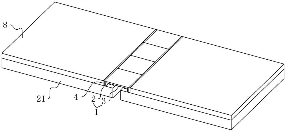
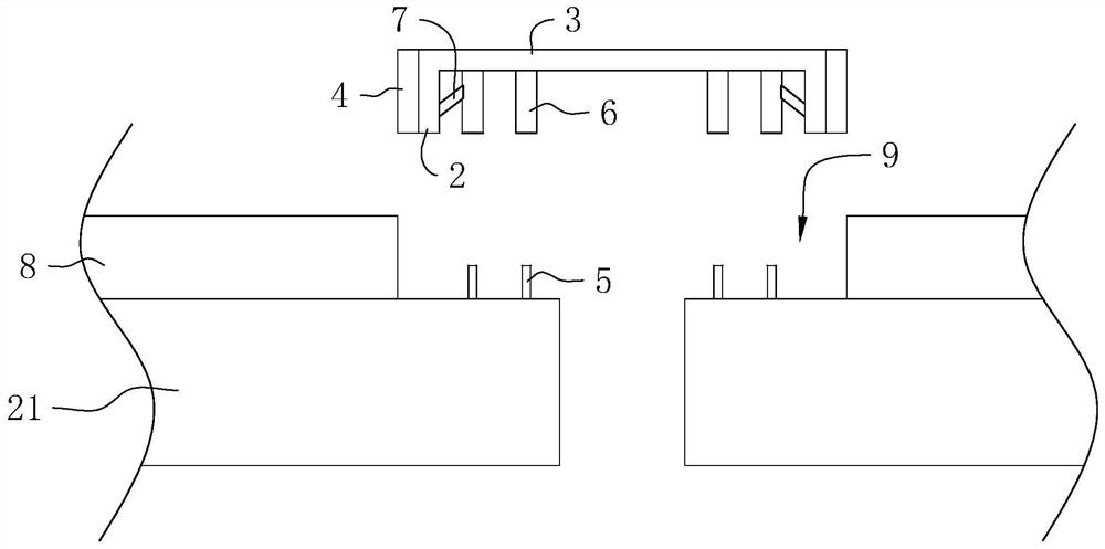
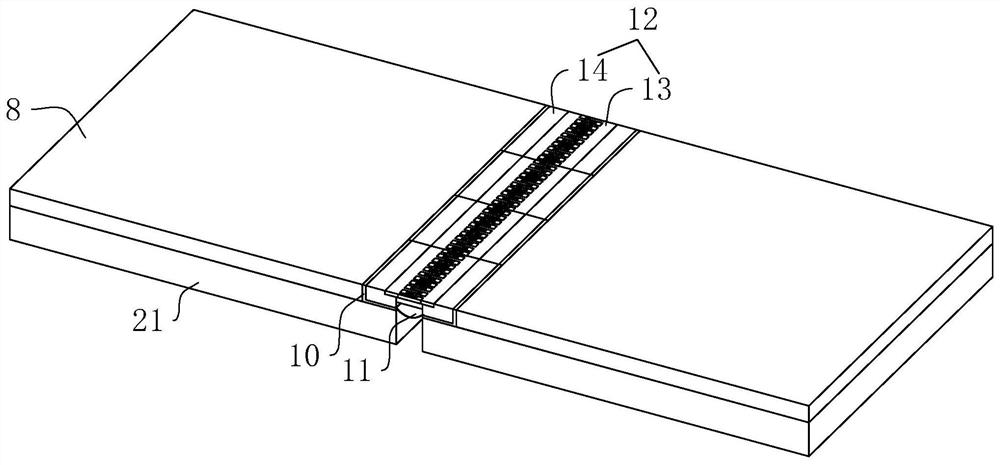
[0036] The embodiment of the application discloses a construction method of a bridge assembly type expansion joint device. refer to figure 1 and figure 2 , the construction method includes the following steps:

[0037] Step 1. A temporary support is built between the ends of two adjacent beams 21 that are used to build the bridge. The temporary support includes a plurality of unit sections 1, and the unit sections 1 include support plates 3 and are integrally formed on the support plates. 3 The two baffles 2 on the opposite side walls, the length direction of the support plate 3 is set along the length direction of the bridge, the two ends of the support plate 3 respectively extend to one end of the adjacent two beams 21, the baffles 2 are vertically arranged and the lower ends abut against each other On the upper surface of the beam body 21, the height of the baffle 2 is made a...


PUM


Abstract

The invention relates to a bridge assembly type expansion joint device construction method which comprises the following steps that 1, a temporary supporting piece is built between the ends, close to each other, of two adjacent beam bodies used for building a bridge, wherein the temporary supporting piece comprises a supporting plate and two baffles arranged on the two opposite side walls of the supporting plate correspondingly; the two ends of the supporting plate extend to one ends of the two adjacent beam bodies correspondingly, the baffle is vertically arranged, the lower end of the baffle abuts against the upper surfaces of the beam bodies, and the supporting plate is provided with a positioning piece used for limiting the supporting plate from disengaging from the beam bodies; 2, concrete is poured on the upper surface of the beam body to form a concrete bridge floor, and a reserved groove used for installing an expansion joint device is formed in the beam body area corresponding to the supporting plate; and 3, after the concrete is solidified and cured, when the expansion joint device needs to be installed, positioning of the supporting plate by the positioning piece is canceled, the supporting plate is taken down, the reserved groove is cleaned, and then the expansion joint device is installed in the reserved groove. The method has the effect of improving the negative effect caused by grooving in the prior art.

Description

technical field [0001] The present application relates to the field of expansion joint devices, in particular to a construction method for bridge-assembled expansion joint devices. Background technique [0002] At present, on large bridges, multiple expansion joint devices are generally installed to adjust the displacement and connection between the superstructure caused by vehicle loads and bridge building materials, so as to reduce the probability of safety accidents [0003] The construction process of the expansion joint device in the related art is as follows: 1. Groove in the gap reserved between two adjacent beam bodies, and deal with the sundries in the groove and the gap; 2. Straighten out the reserved steel bars in the groove; Install the expansion joint device in the groove, and weld the reserved steel bars on the expansion joint device and the reserved steel bars in the groove firmly; 4. Pour concrete in the area where the steel bars in the groove and the reserve...

Claims


Application Information

Patent Timeline
Patent Type & Authority Applications(China)
IPC IPC(8): E01D19/06E01D21/00
CPCE01D19/06E01D21/00
Inventor 王宪旺周思梅曾凡金曾凡文龙始雄
Owner 湖南发通路桥集团有限公司
Learn More