Three-stage gear pump

A technology of gear pumps and driven gears, which is applied in the direction of pumps, pump control, rotary piston pumps, etc., to achieve the effect of improving working conditions and efficiency

Pending Publication Date: 2021-06-04
邵立坤
View PDF5 Cites 0 Cited by
  • Summary
  • Abstract
  • Description
  • Claims
  • Application Information

AI Technical Summary

Problems solved by technology

[0004] However, in some existing working conditions, not only the gear pump is required to be able to adjust the displacement output at low pressure, but also the gear pump is required to be able to output high-pressure medium, but the current conventional gear pumps cannot meet this requirement

Method used


Image

  • Three-stage gear pump
  • Three-stage gear pump
  • Three-stage gear pump

Examples


Embodiment Construction

[0028] The technical solutions of the present invention will be further described in detail below in conjunction with the accompanying drawings and embodiments.

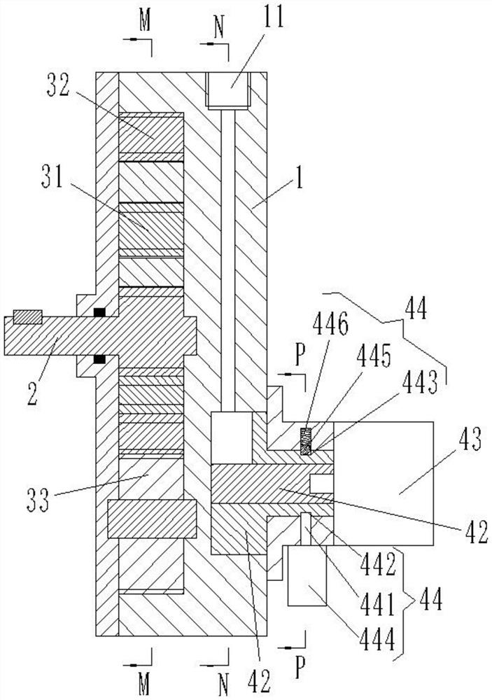
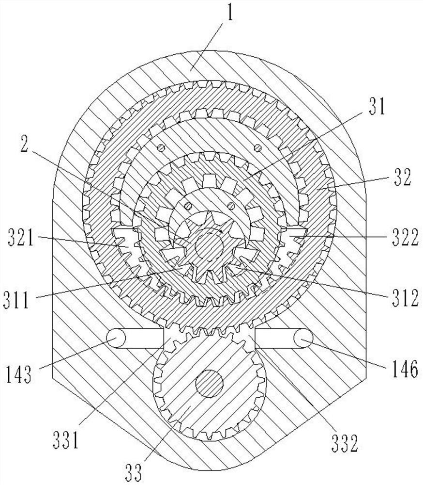
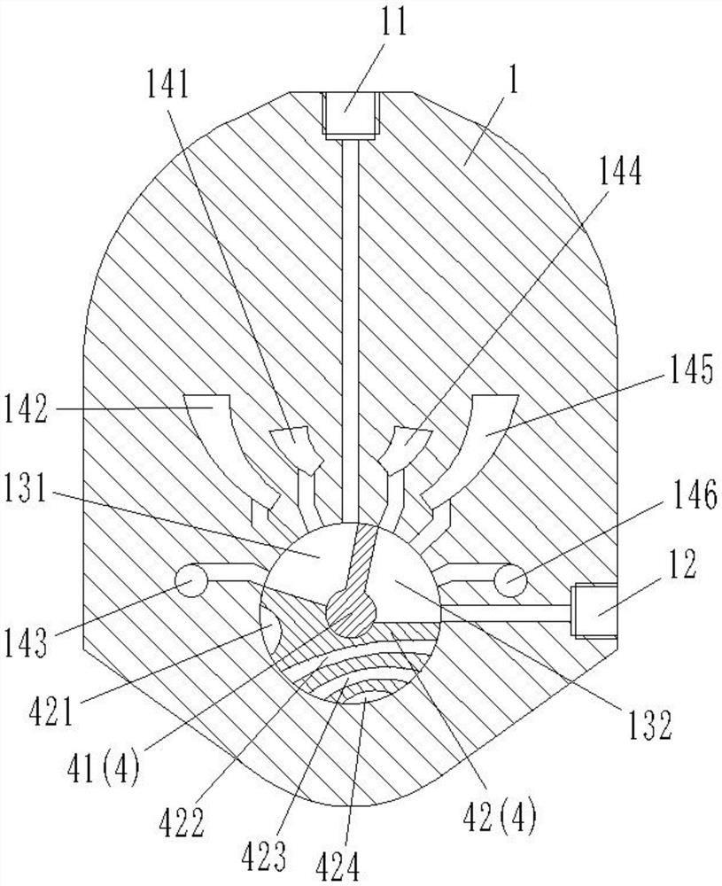
[0029] combine Figure 1 to Figure 8 As shown, the three-stage gear pump in this embodiment includes a pump body 1 , a driving gear 2 , a first driven gear 31 , a second driven gear 32 , a third driven gear 33 and a variable displacement assembly 4 .

[0030] The pump body 1 is provided with an oil inlet 11 connected to an external low-pressure pipeline and an oil outlet 12 connected to an external high-pressure pipeline. In this embodiment, the driving gear 2 adopts a gear shaft structure, and one end is located outside the pump body 1 to connect with external driving equipment, and the other end is located inside the pump body 1 .

[0031] The first driven gear 31, the second driven gear 32 and the third driven gear 33 are all located inside the pump body 1, and the first driven gear 31 and the second driven gear ...


PUM


Abstract

The invention provides a three-stage gear pump. The three-stage gear pump comprises a driving gear, a first driven gear, a second driven gear, a third driven gear and a variable component; tooth meshing transmission connection is formed among the driving gear, the first driven gear, the second driven gear and the third driven gear, a first oil suction cavity and a first oil discharge cavity are formed in the meshing position of the first driven gear, a second oil suction cavity and a second oil discharge cavity are formed in the meshing position of the second driven gear, a third oil suction cavity and a third oil discharge cavity are formed in the meshing position of the third driven gear, and the variable assembly can control the communication relation among an oil inlet, an oil outlet, the first oil suction cavity, the second oil suction cavity, the third oil suction cavity, the first oil discharge cavity, the second oil discharge cavity and the third oil discharge cavity, and therefore, the three-stage gear pump disclosed by the invention can be switched between three-stage pressurization output and variable displacement output, and has higher use efficiency.

Description

technical field [0001] The invention belongs to the technical field of gear pumps, and in particular relates to a three-stage gear pump. Background technique [0002] The gear pump is a rotary pump that relies on the change and movement of the working volume formed between the pump cylinder and the meshing gear to deliver or pressurize the liquid. A gear pump with a general structure is composed of two gears, the pump body and the front and rear covers. When the gears rotate, the volume of the space on the side where the gears are disengaged increases from small to large, forming a vacuum, sucking the liquid, and the space on the gear meshing side. The volume of the space changes from large to small, and the liquid is squeezed into the external pipe. [0003] The gear pump has the advantages of simple structure, small size, light weight, few parts, good manufacturability, easy manufacture, convenient maintenance, low price, good self-priming performance, etc., and is not se...

Claims


Application Information

Patent Timeline
Patent Type & Authority Applications(China)
IPC IPC(8): F04C2/10F04C2/20F04C11/00F04C14/00
CPCF04C2/101F04C2/102F04C2/20F04C11/001F04C14/00
Inventor 不公告发明人
Owner 邵立坤
Why Eureka
Try Eureka