Eureka AIR delivers breakthrough ideas for toughest innovation challenges, trusted by R&D personnel around the world.

Garbage incinerator system and garbage incineration flue gas purification hearth catalytic removal method

A garbage incinerator and garbage technology, applied in the direction of incinerator, combustion method, combustion type, etc., can solve the problems of high input cost, large equipment volume, limited removal efficiency of harmful gases and carcinogens, etc., and reduce environmental hazards Effect

Active Publication Date: 2021-06-04
SHANDONG UNIV
View PDF21 Cites 1 Cited by
  • Summary
  • Abstract
  • Description
  • Claims
  • Application Information

AI Technical Summary

Problems solved by technology

Although very high removal efficiency can be achieved, problems such as large equipment volume and high input cost limit the widespread use of the technology
The inventor found that for small industrial boilers such as waste incinerators, due to cost and volume limitations, the removal efficiency of harmful gases and carcinogens is very limited

Method used


Image

  • Garbage incinerator system and garbage incineration flue gas purification hearth catalytic removal method
  • Garbage incinerator system and garbage incineration flue gas purification hearth catalytic removal method
  • Garbage incinerator system and garbage incineration flue gas purification hearth catalytic removal method

Examples


Embodiment

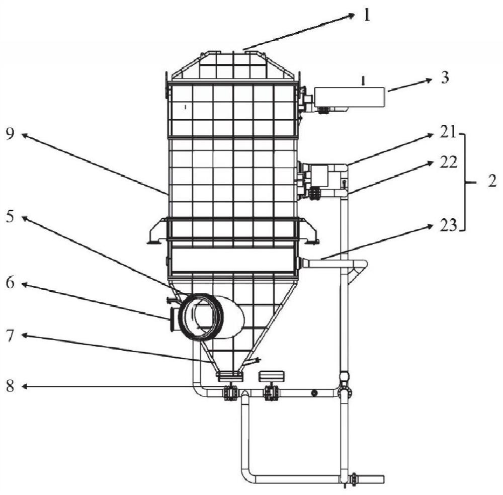
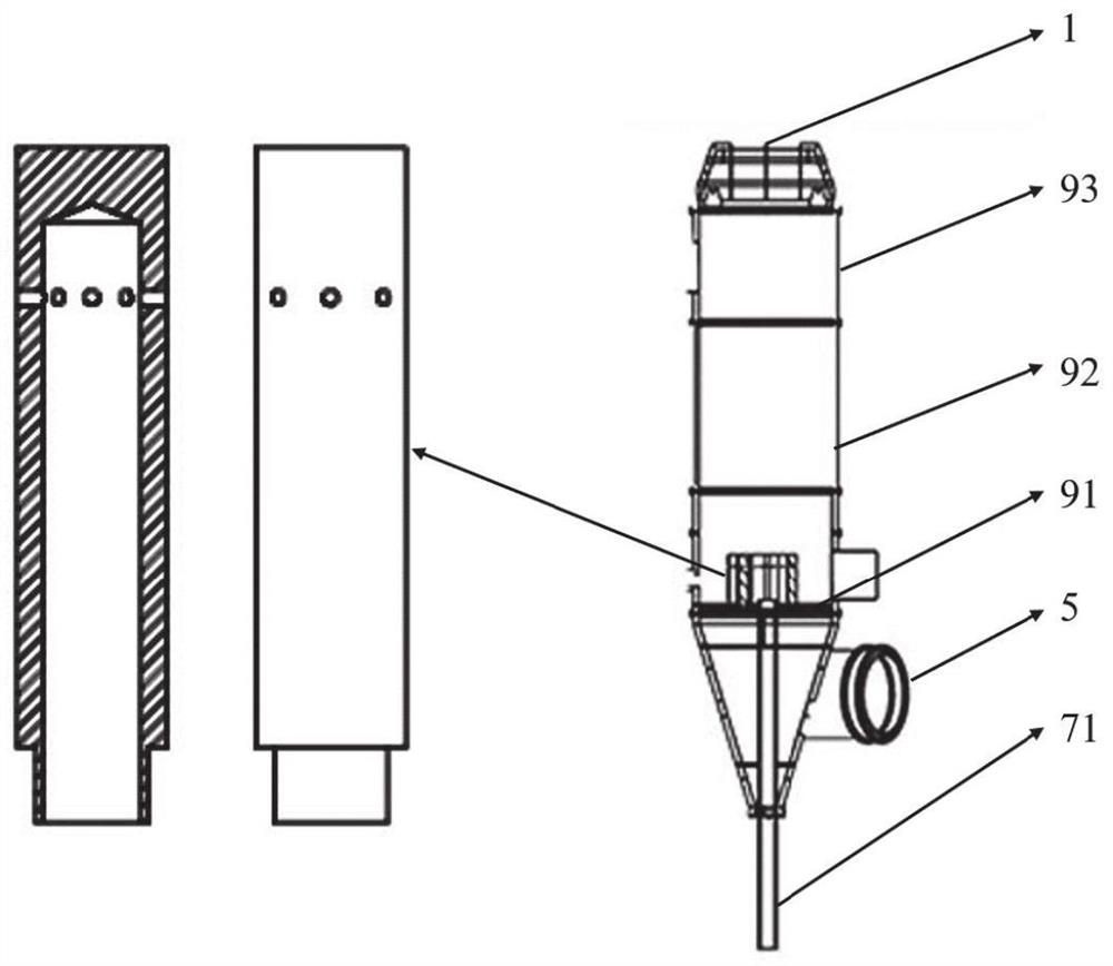
[0084] A waste incinerator system such as Figure 1~3 As shown, it includes: furnace outlet 1, chimney 2, tertiary tuyere 21, secondary tuyere 22, primary tuyere 21, hood baffle 3, peripheral steel frame structure 4, air inlet 5, material inlet 6, equal pressure air chamber 7 , cold slag pipe 71, slag drop port 8, furnace main body 9, chlorine inhibitor 91 in the boiling vertical section, catalytic refractory material 92 in the boiling section, and catalytic refractory material 93 in the suspension section.

[0085] The catalytic refractory material 93 in the top suspension section can replace the original furnace wall refractory material in the suspension section with the top furnace wall refractory material. In actual operation, it can combine the original CO of the flue gas to reduce the NO x Catalyzed removal.

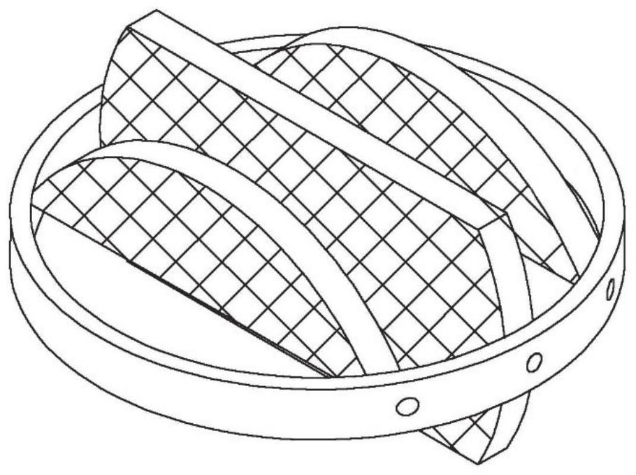
[0086] The boiling section catalytic refractory material 92 replaces the original boiling section furnace wall, air distribution plate 3 and surface refractory ma...


PUM


Abstract

The invention discloses a garbage incinerator system and a garbage incineration flue gas purification hearth catalytic removal method. The garbage incinerator system comprises a garbage incinerator; a flue gas outlet of the garbage incinerator is connected with a flue; a heat exchange device is arranged at the flue gas outlet of the garbage incinerator; a garbage throwing opening of the garbage incinerator is provided with a mixing device; the mixing device is connected with a garbage source and a chlorine inhibitor source; a heat-preservation high-temperature catalyst layer is arranged on the furnace wall of a boiling section of a hearth of the garbage incinerator; heat-preservation medium-temperature catalyst layers are arranged on the furnace wall of a suspension section of the hearth of the garbage incinerator and the inner wall of the flue; a heat storage ball layer is laid on the surface of the heat exchange device; the chlorine inhibitor is formed by compounding sulfur-containing carbon and calcium oxide; the heat preservation high-temperature catalyst is formed by compounding a refractory material and a high-temperature catalyst; the heat-preservation medium-temperature catalyst is formed by compounding a refractory material and a medium-temperature catalyst; and catalytic active components are contained in the heat storage balls. According to the garbage incinerator system and the garbage incineration flue gas purification hearth catalytic removal method, the external treatment cost of the flue gas and the fly ash can be effectively reduced, and inhibition of dioxin during generation and decomposition of products obtained after incineration are effectively achieved.

Description

technical field [0001] The invention belongs to the technical field of garbage incineration, and relates to a garbage incinerator system and a catalytic removal method for a garbage incineration flue gas purification furnace. Background technique [0002] The information disclosed in this background section is only intended to increase the understanding of the general background of the present invention, and is not necessarily taken as an acknowledgment or any form of suggestion that the information constitutes the prior art already known to those skilled in the art. [0003] With the development of the economy, the development of industry is constantly accelerating, and the speed of human consumption of products is also increasing. What modernization brings to human beings is not only the convenience of life and the advancement of science and technology. At the same time, it also brings serious pollution to the environment. Waste incinerators, industrial boilers, and power ...

Claims


Application Information

Patent Timeline
Patent Type & Authority Applications(China)
IPC IPC(8): F23G7/00F23G7/07F23G5/027F23G5/46F23G5/44F23J11/00F23J1/00
CPCF23G7/00F23G7/07F23G5/027F23G5/46F23G5/44F23J11/00F23J1/00Y02A50/20
Inventor 程星星程嘉豪王志强李向东
Owner SHANDONG UNIV
Why Eureka
Eureka Blog
Learn More