
Tension testing device and method for eddy current brake

A technology for eddy current brakes and tensile testing, which is applied to measuring devices, force/torque/power measuring instruments, instruments, etc., and can solve problems such as inability to meet high and low temperature tensile testing requirements

Active Publication Date: 2021-06-04
CRRC QINGDAO SIFANG ROLLING STOCK RES INST
View PDF6 Cites 0 Cited by
  • Summary
  • Abstract
  • Description
  • Claims
  • Application Information

AI Technical Summary

Problems solved by technology

[0005] The purpose of the present invention is to provide a tensile test device for eddy current brakes, to solve the technical problem in the above-mentioned prior art that the requirements for high and low temperature tensile tests of the eddy current brake Y to the connecting part cannot be met.

Method used


Image

  • Tension testing device and method for eddy current brake
  • Tension testing device and method for eddy current brake
  • Tension testing device and method for eddy current brake

Examples


Embodiment Construction

[0060]In the following, the present invention will be specifically described through exemplary embodiments. It should be understood, however, that elements, structures and characteristics of one embodiment may be beneficially incorporated in other embodiments without further recitation.

[0061] In the description of the present invention, it should be noted that the terms "inner", "outer", "upper", "lower", "front", "rear", "first", "second", "third", "fourth" The orientation or positional relationship indicated by etc. is based on the positional relationship shown in the drawings, and is only for the convenience of describing the present invention and simplifying the description, rather than indicating or implying that the referred device or element must have a specific orientation or be constructed in a specific orientation. and operation, and therefore should not be construed as limiting the invention.

[0062] In the description of the present invention, "installation", ...


PUM


Abstract

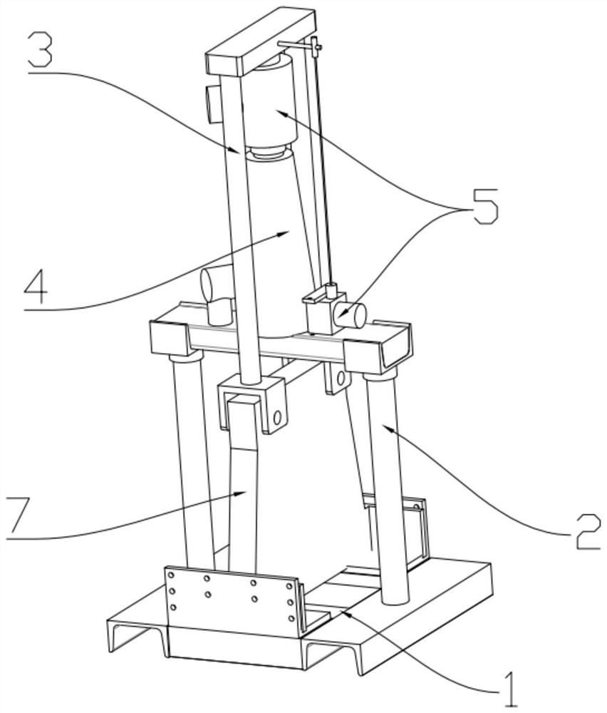
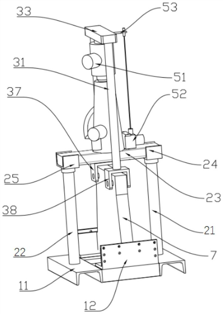
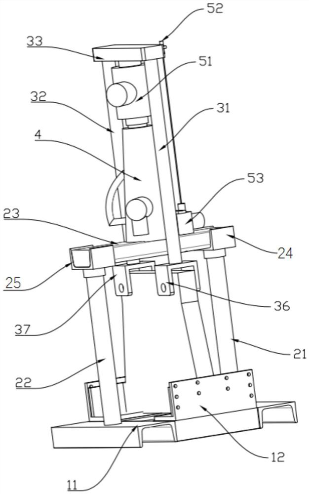
The invention discloses a tension testing device and a tension testing method for an eddy current brake. The tension testing device comprises a base and a load applying assembly, a tested piece is placed on the base; the load applying assembly comprises a first supporting frame, a second supporting frame and a load applying piece. The first supporting frame is arranged on the base, a first accommodating space is formed between the top end of the first supporting frame and the base, and a tested piece is arranged in the first accommodating space; the bottom end part of the second support frame is connected with the tested piece, the top end part of the second support frame is positioned above the top end part of the first support frame, and a second accommodating space is formed between the top end part of the second support frame and the top end part of the first support frame; the load applying piece is located in the second containing space and fixedly arranged at the top end of the first supporting frame, the load output end of the load applying piece is connected with the top end of the second supporting frame, and the data collecting assembly is connected with the load applying piece. The technical problem of high and low temperature tension test requirements of the Y-direction connection subassembly of the eddy current brake in the prior art is solved.

Description

technical field [0001] The invention relates to the technical field of measuring equipment, in particular to a tensile test device and a test method for an eddy current brake. Background technique [0002] The eddy current brake is suitable for the braking requirements of high-speed rail vehicles running at high speed. The Y-direction (vehicle transverse) connection part is an important part of the eddy current brake body. When the braking effect occurs, the Y-direction connection part can realize the Y The transmission to the electromagnetic attraction provides braking force to the train while releasing the X-direction (vehicle longitudinal) degree of freedom. [0003] In the prior art, in order to ensure the gap between the magnetic pole and the lateral track plate, it is usually necessary to apply a certain preload to the rubber spring installed in the Y-direction connecting part during assembly. In order to make the preload installed on the connecting part along the Y d...

Claims


Application Information

Patent Timeline
IPC IPC(8): G01L5/28
CPCG01L5/28
Inventor 丰明阳金星刘楠王炳坤施玉奇杨磊董振威
Owner CRRC QINGDAO SIFANG ROLLING STOCK RES INST
Learn More