
In-situ loading device and method for fiber drawing test of fiber concrete

A pull-out test and in-situ addition technology, applied in measuring devices, using stable tension/pressure testing materials, instruments, etc., can solve the problem that the mechanical properties of the interface between the fiber and the matrix cannot be realized, and the complex three-dimensional interface between the fiber and the matrix cannot be realized. space, the inability to obtain the deformation of the fiber matrix interface, etc.

Pending Publication Date: 2021-01-29
CHINA UNIV OF MINING & TECH (BEIJING)
View PDF0 Cites 0 Cited by
  • Summary
  • Abstract
  • Description
  • Claims
  • Application Information

AI Technical Summary

Problems solved by technology

However, the damage and destruction of the fiber-matrix interface is a complex three-dimensional space problem. The deformation at the fiber-matrix interface inside the specimen cannot be obtained through the above analysis alone, and the quantitative characterization of the mechanical properties of the fiber-matrix interface cannot be realized.

Method used


Image

  • In-situ loading device and method for fiber drawing test of fiber concrete

Examples


Embodiment Construction

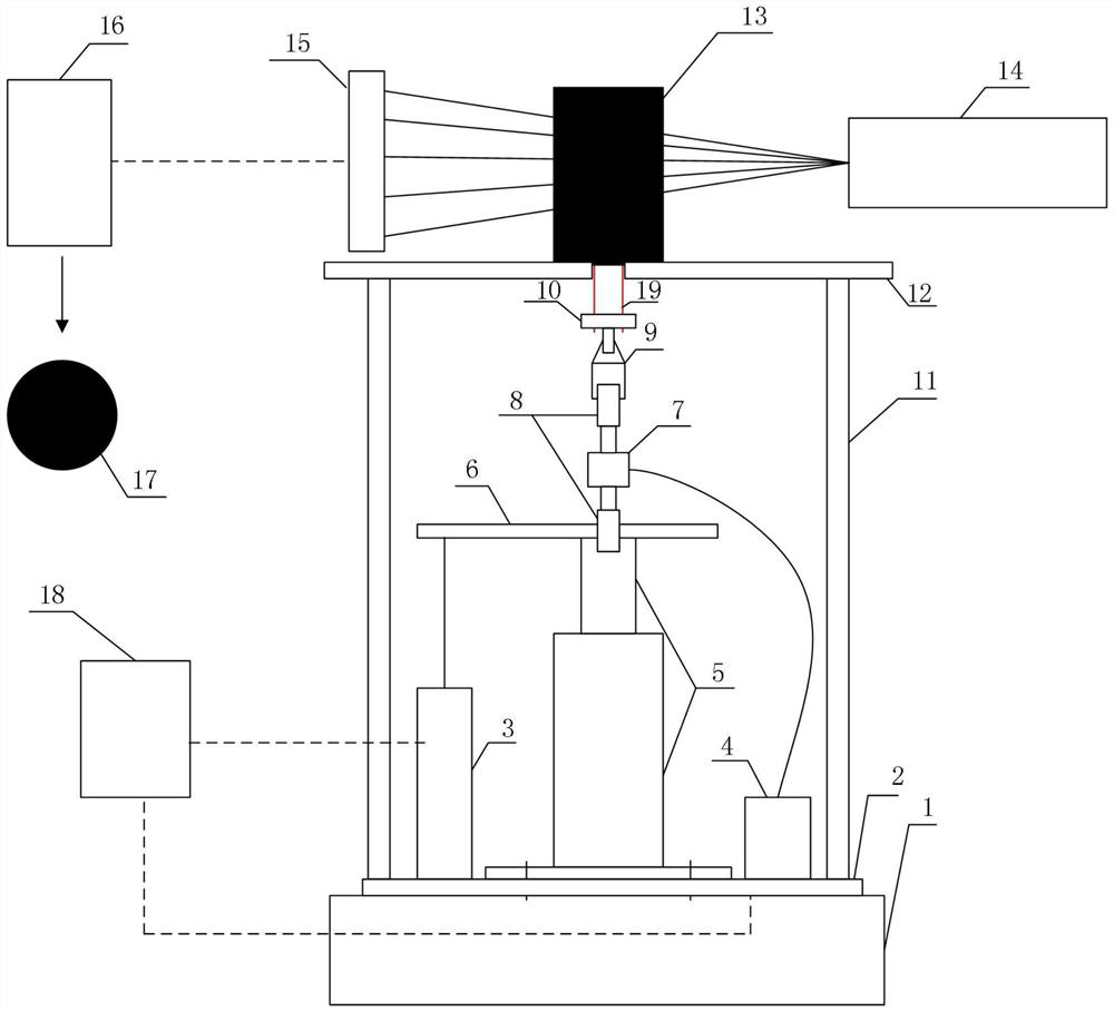
[0018]byfigure 1It can be seen that the in-situ loading device for the fiber pull test includes a rotating platform (1), a support base (2), a displacement meter (3), a transmitter (4), an electric tension (compression) rod (5), and a thin steel plate ( 6) Tension (compression) force sensor (7), connecting piece (8), chuck (9), fastening conversion piece (10), steel column (11), supporting top plate (12), X-ray source (14) ), detector (15), image acquisition device (16), data acquisition device (18);

[0019]The load platform is connected with the electric tension (compression) rod, the electric tension (compression) rod is connected with the tension (compression) force sensor through the connector, and the tension (compression) force sensor is connected with the chuck through the connector, and the chuck and tightening are switched Connecting parts, fasten the conversion part and fiber connection, the thin steel plate is connected with the electric tension (compression) rod, the displ...


PUM


Abstract

The invention discloses an in-situ loading device and method for a fiber drawing test of fiber concrete. The invention relates to the technical field of engineering nondestructive testing. The in-situloading device for the fiber drawing test of the fiber concrete consists of an X-ray scanning system, an in-situ loading system and a data acquisition system, the device specifically comprises a loading rotating platform, a supporting bottom plate, a displacement meter, a transmitter, an electric tension (compression) rod, a thin steel plate, a tension (compression) force sensor, a connecting piece, a chuck, a fastening conversion piece, a steel column, a supporting top plate, an X-ray source, a detector, an image acquisition device and a data acquisition device. According to the invention, in-situ loading detection of a fiber concrete single fiber and multiple fiber drawing tests can be realized, and a CT scanning image inside a test piece in the process of pulling out fibers from a concrete matrix can be obtained, so that the deformation condition at the interface of the fiber matrix in the process is obtained; and conditions are provided for quantitative characterization of interface mechanical properties between fibers and the matrix.

Description

Technical field[0001]The invention belongs to the technical field of non-destructive testing, and specifically provides a loading device and method for in-situ tensile experiments of industrial CT.Background technique[0002]Concrete is one of the most important civil engineering materials in modern times. It is a brittle material with low tensile strength and fracture toughness. Incorporating random-distributed short fibers into concrete can effectively prevent the expansion of micro-cracks and the formation of macro-cracks in the concrete, and improve the tensile, flexural, impact and fracture toughness of concrete. In recent years, fiber concrete has been widely used in various professional fields such as construction engineering, water conservancy engineering, highway and bridge engineering, highway pavement and airport pavement engineering, and railway lines.[0003]The interface between the fiber and the matrix in fiber concrete plays a role in transferring stress between the fibe...

Claims


Application Information

Patent Timeline
Patent Type & Authority Applications(China)
IPC IPC(8): G01N3/06G01N3/08
CPCG01N3/06G01N3/08G01N2203/0003G01N2203/0017G01N2203/0067G01N2203/028G01N2203/0641
Inventor 毕玉洁毛灵涛刘海洲
Owner CHINA UNIV OF MINING & TECH (BEIJING)
Learn More