Type-C connector structure and production process thereof

A joint structure, the same end technology, applied in the direction of fixed/insulated contact members, connections, parts of connecting devices, etc., can solve the problems affecting product ejection and yield, complex structure, complicated mold design, etc., to improve the ejection rate. , The effect of simplifying the internal structure and compact structure

Pending Publication Date: 2021-06-04
东莞林全电子科技有限公司
View PDF0 Cites 0 Cited by
  • Summary
  • Abstract
  • Description
  • Claims
  • Application Information

AI Technical Summary

Problems solved by technology

[0002] Existing Type-C connectors all require mold molding and processing. However, the existing Type-C connectors have a complex structure, resulting in complex mold design, which affects product release and yield

Method used


Image

  • Type-C connector structure and production process thereof
  • Type-C connector structure and production process thereof
  • Type-C connector structure and production process thereof

Examples


Embodiment 1

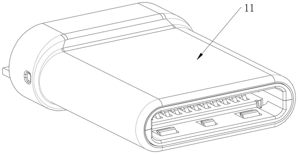
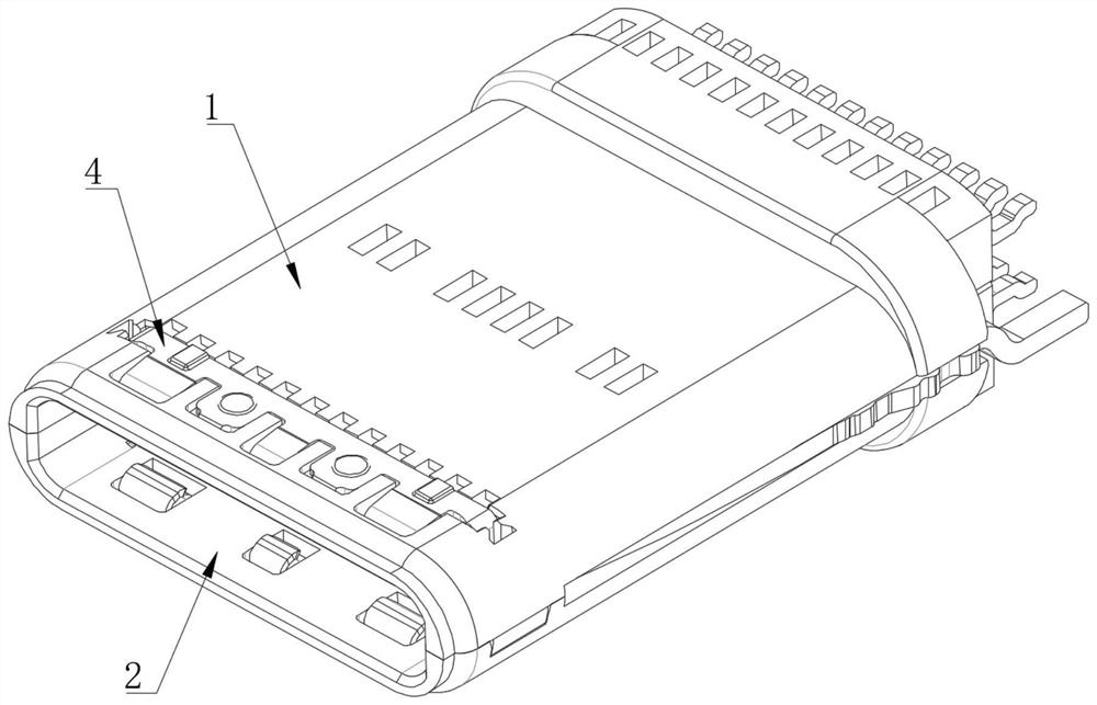
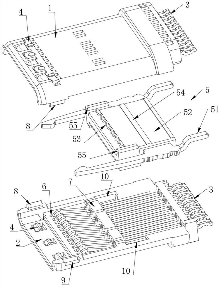
[0032] Example 1: A Type-C connector structure, see Figure 1 to 4 The first rubber shell 1 and the second rubber case 2 including a mirror symmetrical mounted, the first rubber shell 1 and the inner wall of the second rubber housing 2 are respectively mounted with a row correspondingly provided terminal 3, the first The EMI sheet 4 is mounted in the same end of the adhesive shell 1 and the second rubber shell 2, and the first rubber shell 1 and the second rubber shell 2 are mounted to insulation and positioning two row terminals 3. The septum 5.

[0033] The first rubber shell 1 and the second rubber housing 2 mounted in a mirror symmetrical mounted, reducing the mold design structure, increase the mold rate, the product is higher, and by setting a septum 5, simultaneously playing up and down two rows The terminal 3 and the effect of the insulation simplifies the internal structure of the Type-C connector so that the structure is more compact.

[0034] In the present embodiment, t...

Embodiment 2

[0044] Example 2: A Type-C connector structure production process, including the following steps:

[0045] S1, the two rows of terminals and two EMI sheets are mounted on the upper and lower inclusions;

[0046] S2, mount the middle spacer between the two rubber shells;

[0047] S3, assembled two rubber shells;

[0048] S4, ultrasonic welding two rubber shell;

[0049] S5, test by visual pairing device;

[0050] S6, give the outer casing through the test.

[0051] In the present embodiment, the terminal production uses a small Pith process, two terminals, reducing the risk of stamping die terminals, and improving the punching speed, and improve production efficiency.

[0052] Ultrasonic welding is more beautiful, better sealing; high detection efficiency is high, improved product yield; the production step is simple and easy to operate, and production efficiency is improved.

[0053] Preferably, the head of the terminal is bent and processed. This ensures that the terminal bullet ...


PUM


Abstract

The invention relates to the technical field of Type-C connectors, and particularly relates to a Type-C connector structure and a production process thereof. The Type-C connector structure and the production process thereof are technically characterized in that the Type-C connector structure comprises a first rubber shell and a second rubber shell which are installed in a mirror symmetry mode, and the inner wall of the first rubber shell and the inner wall of the second rubber shell are each provided with a row of terminals which are correspondingly arranged; and the same ends of the first rubber shell and the second rubber shell are respectively provided with an EMI sheet, and a middle spacer used for insulating and positioning the two rows of terminals is installed between the first rubber shell and the second rubber shell. The first rubber shell and the second rubber shell are installed in a mirror symmetry mode, a mold design structure is reduced, a mold stripping rate is improved, the product yield is higher, in addition, the middle spacer is arranged, the effects of positioning the upper row of terminals and the lower row of terminals and insulating are achieved at the same time, the internal structure of the Type-C connector is simplified, and the structure is more compact.

Description

Technical field [0001] This application relates to the field of TYPE-C connecting head, and more particularly, it involves a TYPE-C joint structure and its production process. Background technique [0002] Existing Type-C connections require mold forming processing, however, the existing Type-C connector structure is complex, causing complex mold design, affecting product outlet and yield. Inventive content [0003] In response to the shortcomings of the above prior art, the first object of this application is to provide a TYPE-C connector structure, which has the advantages of simple structure, easy and high product extension. [0004] The above technical object of the present application is to be implemented by the following technical solution: a TYPE-C connector structure including a first rubber housing and a second rubber case showing a mirror symmetrical mounted, the first rubber shell and the second The inner wall of the rubber shell is provided with a row of correspondin...

Claims


Application Information

Patent Timeline
IPC IPC(8): H01R13/502H01R13/42H01R43/20
CPCH01R13/42H01R13/502H01R43/20
Inventor 李国栋
Owner 东莞林全电子科技有限公司
Why Eureka
Try Eureka