Pusher for circuit board processing

A technology of pusher and circuit board, which is applied in the direction of printed circuit, printed circuit manufacturing, electrical components, etc., can solve the problems of reducing work efficiency, interrupting the processing process, and interrupting material pushing, so as to realize automatic opening and closing, save time, The effect of improving productivity

Active Publication Date: 2021-06-04
深圳市新锐霖电子有限公司
View PDF6 Cites 0 Cited by
  • Summary
  • Abstract
  • Description
  • Claims
  • Application Information

AI Technical Summary

Problems solved by technology

[0002] According to the number of layers, the circuit board is divided into three major categories: single-sided board, double-sided board, and multi-layer circuit board. It is a printed board with conductive patterns interconnected as required. The multilayer circuit board is the product of the development of electronic information technology in the direction of high speed, multi-function, large capacity, small volume, thinner and lighter weight. The current circuit board In the production process, a pusher is often needed to push the material, but the current pusher often has some problems when it is used, causing the push to be interrupted;
[0003] When the current pusher is in use, because the feeding head of the pusher is made of metal, the cooling speed of the metal material is fast during use, which will cause the raw materials to cool and solidify at the top of the pusher when the feeding is stopped. , causing the blockage of the pusher, affecting the subsequent use of the pusher, interrupting the processing process, reducing work efficiency, and reducing production revenue

Method used


Image

  • Pusher for circuit board processing
  • Pusher for circuit board processing
  • Pusher for circuit board processing

Examples


Embodiment Construction

[0021] The following will clearly and completely describe the technical solutions in the embodiments of the present invention with reference to the accompanying drawings in the embodiments of the present invention. Obviously, the described embodiments are only some, not all, embodiments of the present invention. Based on the embodiments of the present invention, all other embodiments obtained by persons of ordinary skill in the art without making creative efforts belong to the protection scope of the present invention.

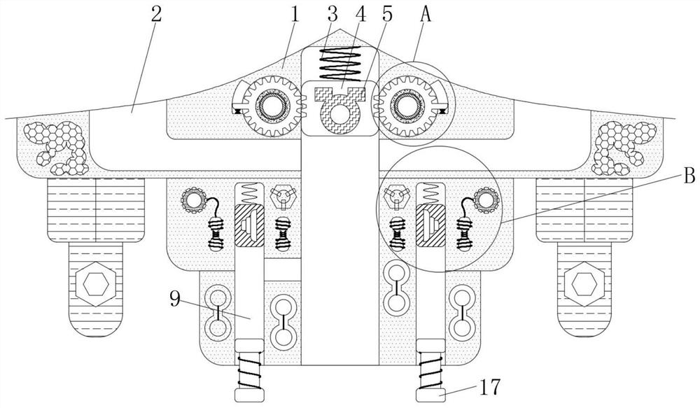
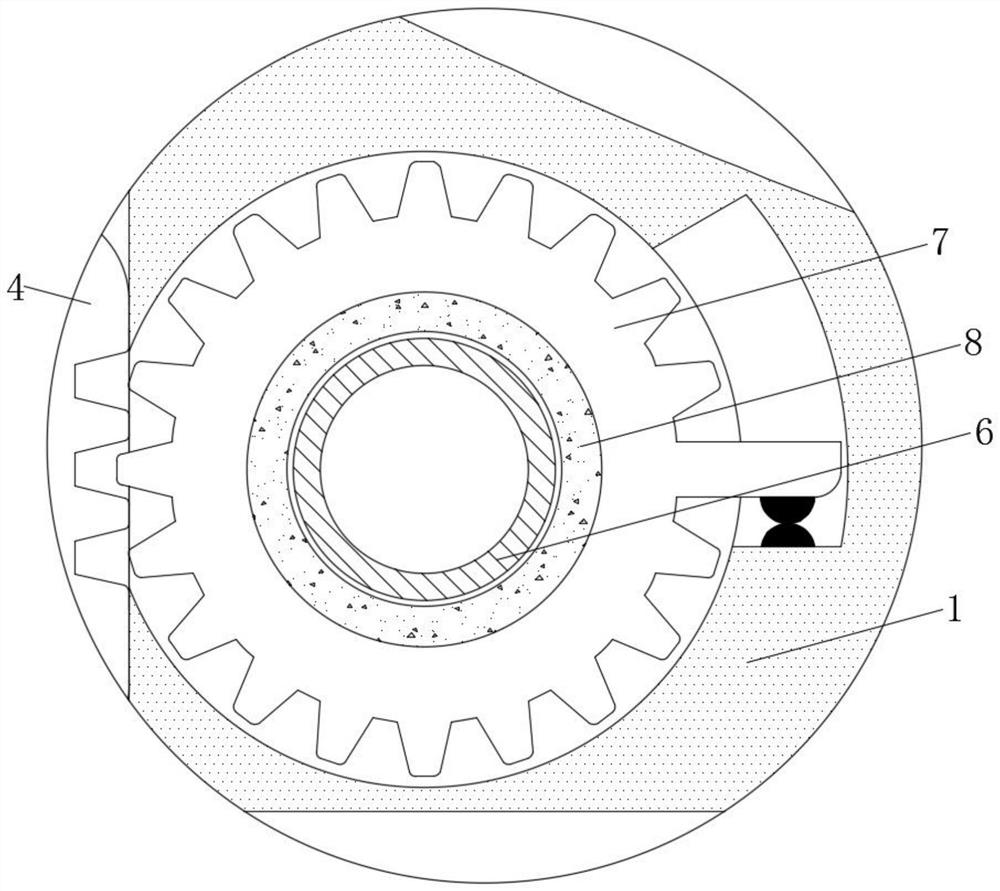
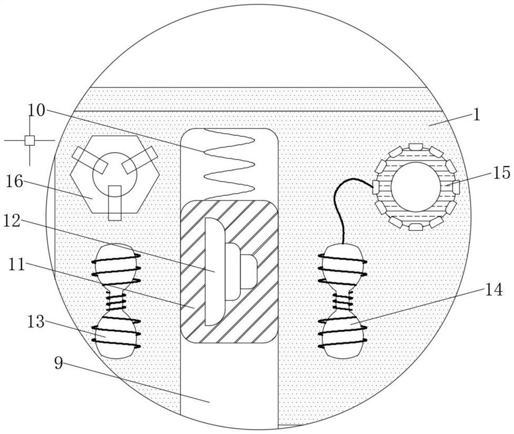
[0022] see Figure 1-6 , a pusher for circuit board processing, including a pusher head 1, the material of the pusher head 1 is a hard high-strength material and the pusher head 1 does not have magnetic conductivity and conductivity, and the pusher head 1 To fix the parts, the inside of the feeding chamber 2 is filled with raw materials, the spring one 3 is a compression spring and the diameter of the spring one 3 is smaller than the size of the pushing head 1...


PUM


Abstract

A pusher for circuit board processing relates to the technical field of circuit board processing and comprises a pushing head, the inner wall of the pushing head is provided with a feeding cavity, the inner top wall of the pushing head is fixedly connected with a first spring, the bottom of the first spring is fixedly connected with a top block, the middle of the top block is fixedly connected with a magnetic block, the inner wall of the pushing head is fixedly connected with a first friction ring, a tooth block is movably connected with the inner wall, close to the outer side of the first friction ring, of the pushing head, a second friction ring is fixedly connected with the inner wall of the tooth block, an air groove is formed in the bottom of the pushing head, and a second spring is fixedly connected with the inner top wall of the air groove. According to the pusher for circuit board processing, through cooperative use of an ejector block and an electromagnet, when the pushing head is blocked, the electromagnet is in a power-on state, and the ejector block can extend downwards under the magnetic attraction action of the electromagnet and a magnetic block to extrude out solid raw materials in the pushing head, so that the effect of automatic cleaning is achieved, time is saved, and the production efficiency is effectively improved.

Description

technical field [0001] The invention relates to the technical field of circuit board processing, in particular to a pusher for circuit board processing. Background technique [0002] According to the number of layers, circuit boards are divided into three major categories: single-sided boards, double-sided boards, and multi-layer circuit boards. It is a printed board with conductive patterns interconnected as required. The multilayer circuit board is the product of the development of electronic information technology in the direction of high speed, multi-function, large capacity, small volume, thinner and lighter weight. The current circuit board In the production process, a pusher is often needed to push the material, but the current pusher often has some problems when it is used, causing the push to be interrupted; [0003] When the current pusher is in use, because the feeding head of the pusher is made of metal, the cooling speed of the metal material is fast during use...

Claims


Application Information

Patent Timeline
Patent Type & Authority Applications(China)
IPC IPC(8): H05K3/00
CPCH05K3/00
Inventor 杨继兵
Owner 深圳市新锐霖电子有限公司
Why Eureka
Try Eureka