Chip mounting system and chip mounting method

A patch system and material paste technology, applied in the direction of electrical components, electrical components, etc., can solve the problems of high-temperature deformation of metal PCB substrates, prone to failure of contact surfaces, and damage to LED chips, etc.

Pending Publication Date: 2021-06-04
PUJIANG SANSI OPTOELECTRONIC TECH CO LTD
View PDF0 Cites 2 Cited by
  • Summary
  • Abstract
  • Description
  • Claims
  • Application Information

AI Technical Summary

Problems solved by technology

[0003] The heat dissipation problem of the LED chip is one of the key points that affect the service life of the LED bulb lamp. If the LED industry wants to achieve large-angle balanced light emission, the conventional process is to indirectly guide the heat of the LED chip after lighting to the metal PCB substrate. On the conical radiator, secondary heat dissipation is required to solve the heating problem of the LED chip, because the contact surface of the secondary heat dissipation is prone to failure, which will lead to high-temperature deformation of the metal PCB substrate and damage the LED chip, affecting the service life of the LED bulb lamp

Method used


Image

  • Chip mounting system and chip mounting method
  • Chip mounting system and chip mounting method
  • Chip mounting system and chip mounting method

Examples


Embodiment Construction

[0055] In order to make the purpose, technical solutions and advantages of the embodiments of the present invention more clear, various implementation modes of the present invention will be described in detail below in conjunction with the accompanying drawings. However, those of ordinary skill in the art can understand that, in each implementation manner of the present invention, many technical details are provided for readers to better understand the present application. However, even without these technical details and various changes and modifications based on the following implementation modes, the technical solution claimed in this application can also be realized.

[0056] In the following description, for the purposes of explaining the various disclosed embodiments, certain specific details are set forth in order to provide a thorough understanding of the various disclosed embodiments. One skilled in the relevant art will recognize, however, that an embodiment may be p...


PUM


Abstract

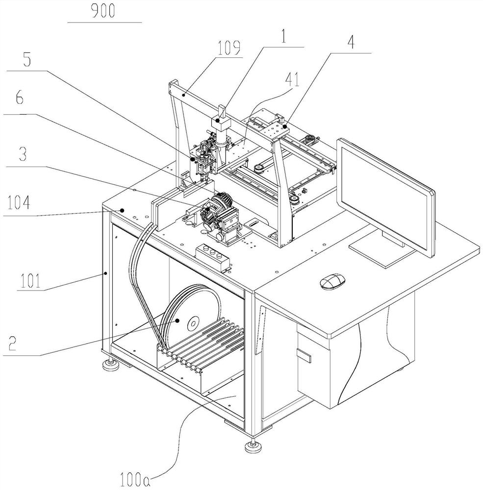
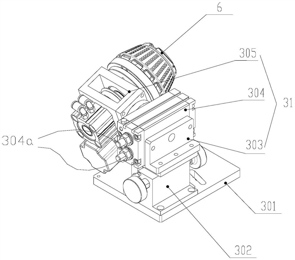
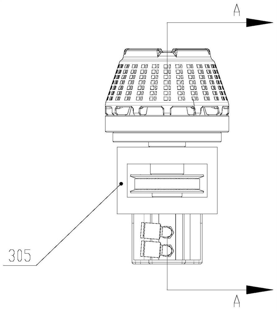
The invention discloses a chip mounting system and a chip mounting method. In the invention, the chip mounting system comprises: a frame, a material taking and chip mounting device arranged on the frame and capable of obtaining workpieces, a positioning clamp, a displacement device, a visual device and a main control module, wherein the positioning clamp is arranged on the frame and can clamp a conical radiator and adjust the position of the conical radiator, and the conical radiator is used for pasting the workpieces obtained by the material taking and chip mounting device; the displacement device is arranged on the frame and is used for driving the material taking and chip mounting device to move relative to the conical radiator; the visual device is arranged on the frame and is used for acquiring line point location information of the workpiece to be attached on the conical radiator; the main control module is electrically connected with the material taking and chip mounting device, the positioning clamp, the displacement device and the visual device; and the main control module is used for controlling the material taking and chip mounting device to place the workpieces on the conical radiator according to the received line point location information. Compared with the prior art, by using the system of the invention, the possibility that the LED chip is damaged due to a heat dissipation problem is eliminated, and fault sources are reduced.

Description

technical field [0001] The invention relates to the field of lamp processing, in particular to a patch system and a patch method. Background technique [0002] Among LED lamps, there is a kind of LED bulb lamp with large angle and balanced light emission. The LED chips on the core light source need to be arranged in a cone shape. At present, the SMT equipment in the LED industry is all flat SMT. If the conventional core light source production process in the LED industry wants to achieve large-angle balanced light emission, it is necessary to first attach the LED chip surface to the flat metal PCB substrate, and then attach the metal PCB substrate. It is installed on a conical heat sink to ensure that the LED chips on the core light source are arranged in a conical shape, and secondary heat dissipation is required to solve the problem of heat generation of the LED chips. [0003] The heat dissipation problem of the LED chip is one of the key points that affect the service l...

Claims


Application Information

Patent Timeline
Patent Type & Authority Applications(China)
IPC IPC(8): H05K13/04
CPCH05K13/0465H05K13/0409
Inventor 郭惠民杨万山胡永宝李晓白
Owner PUJIANG SANSI OPTOELECTRONIC TECH CO LTD
Why Eureka
Try Eureka