Parking lock device and its assembly method

A parking lock and parking technology, applied in transmission control, components with teeth, belts/chains/gears, etc., can solve problems such as increasing installation workload, and achieve the effect of omitting trial engagement and easy installation

Active Publication Date: 2022-08-09
SCHAEFFLER TECH AG & CO KG
View PDF6 Cites 0 Cited by
  • Summary
  • Abstract
  • Description
  • Claims
  • Application Information

AI Technical Summary

Problems solved by technology

It is conceivable to transfer the adjustment work from the park lock wheel / pawl interface to the lock pawl actuation mechanism interface of the lock pawl, such as an electric motor, but this creates the disadvantage that a park lock with an actuator Units are not available as pre-fabricated modules, which increases installation effort

Method used


Image

  • Parking lock device and its assembly method
  • Parking lock device and its assembly method
  • Parking lock device and its assembly method

Examples


Embodiment Construction

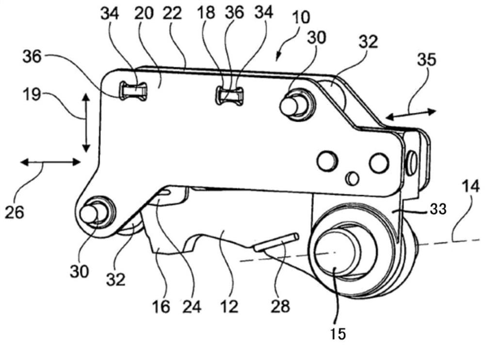
[0031] figure 1 The parking lock device 10 is shown with a locking pawl 12 , which is rotatable about an axis of rotation 14 . When the locking pawl 12 is rotated, the ratchet teeth 16 integrally formed therewith move substantially in the radial direction 19 relative to the main drive shaft (not shown). The parking lock device 10 is intended to be installed in a vehicle transmission of a motor vehicle and to secure a parking lock wheel (not shown) which is connected in a rotationally fixed manner to the main driveshaft. For this purpose, the parking lock wheel has a locking tooth system arranged on its outer circumference, in which locking tooth system the ratchet teeth 16 can be locked in a form-fitting manner.

[0032] The locking pawl 12 is held by a return spring 28 which prevents the locking pawl from inadvertently locking on the parking lock wheel due to gravity in an unloaded state.

[0033]The parking lock device 10 also has a first housing wall 20 and a second housi...


PUM


Abstract

The invention relates to a parking lock device (10) having a parking lock housing (20), a locking pawl (12), an actuating unit (24) and a support element (18), the locking pawl (18). The pawl (12) has a ratchet tooth (16) which can be locked in the parking lock wheel (56) and a pawl profile (44) arranged on the rear side of the ratchet tooth (16), the actuating unit ( 24) Act on the pawl profile (44) when engaging the parking lock device (10) so that the locking pawl (12) is relative to the parking lock housing (20) Rotating about the axis of rotation (14), the actuating unit (24) is supported on the support element (18) in the engaged state (P) and the disengaged state (nP) of the parking lock (10) at different locations. The support element (18) is connected to the parking lock housing (20) with play. The invention also relates to an assembly method of the parking lock device and a vehicle transmission with the parking lock device.

Description

technical field [0001] The present invention relates to a parking lock device, a method of assembling the same, and a transmission having such a parking lock device. Background technique [0002] A parking lock is known, for example, from DE 10144063 A1. It describes a parking lock device in an automatic transmission of a motor vehicle, which parking lock device has a locking ring with a locking groove arranged on the propeller shaft. When the device is in the locked state, the pawl engages the locking groove via the pivotable selector lever and the link connected thereto. The connecting rod has rollers at its ends, wherein a second roller guides the connecting rod in the L-shaped guide. The guide plate is fixed in the housing of the automatic transmission. When the link moves longitudinally, the second roller rolls on the guide. Thus, the guide plate contains side walls and horizontally extending walls. The horizontally extending wall of the guide plate has extension h...

Claims


Application Information

Patent Timeline
Patent Type & Authority Patents(China)
IPC IPC(8): F16H63/34
Inventor 克劳斯·克拉默马蒂亚斯·费尔巴哈马库斯·罗斯特托比亚斯·休曼克里斯托夫·蒂劳夫
Owner SCHAEFFLER TECH AG & CO KG
Why Eureka
Try Eureka