

Component measurement system, measurement device, and measurement tip
A technology for measuring components and measuring devices, which can be applied to measuring devices, sampling devices, blood sampling devices, etc., can solve the problems of increasing the cost of measuring chips, and achieve the effects of being beneficial to mass production, simple setting and low cost.
- Summary
- Abstract
- Description
- Claims
- Application Information
AI Technical Summary
Problems solved by technology
Method used
Image

Examples
no. 1 Embodiment approach 〕
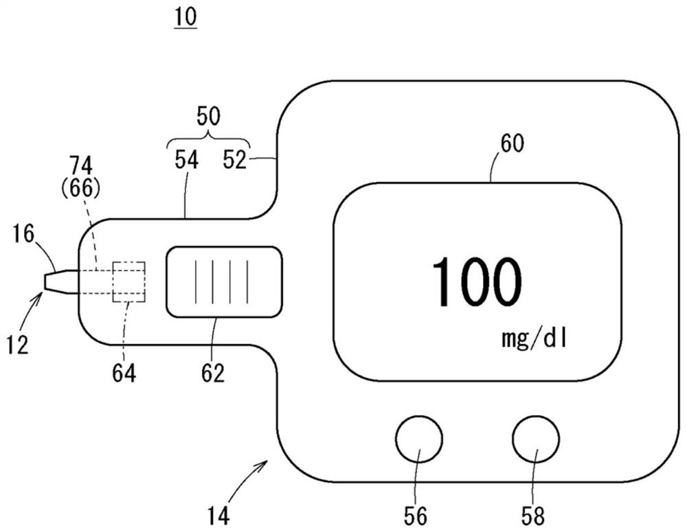
[0036] Such as figure 1 As shown, the component measurement system 10 according to the first embodiment of the present invention is configured as a blood glucose meter for measuring the component amount (blood sugar level) of glucose in blood. Therefore, the component measurement system 10 is also referred to as the blood glucose meter 10 hereinafter.
[0037]The blood glucose meter 10 includes a measurement chip 12 capable of collecting blood from a patient, and a measurement device 14 mounted with the measurement chip 12 and measuring the blood collected by the measurement chip 12 . The measurement chip 12 is configured as a disposable type that is discarded every time a measurement is performed. The measurement device 14 is configured as a reusable type capable of repeatedly measuring the blood sugar level by replacing the measurement chip 12 .
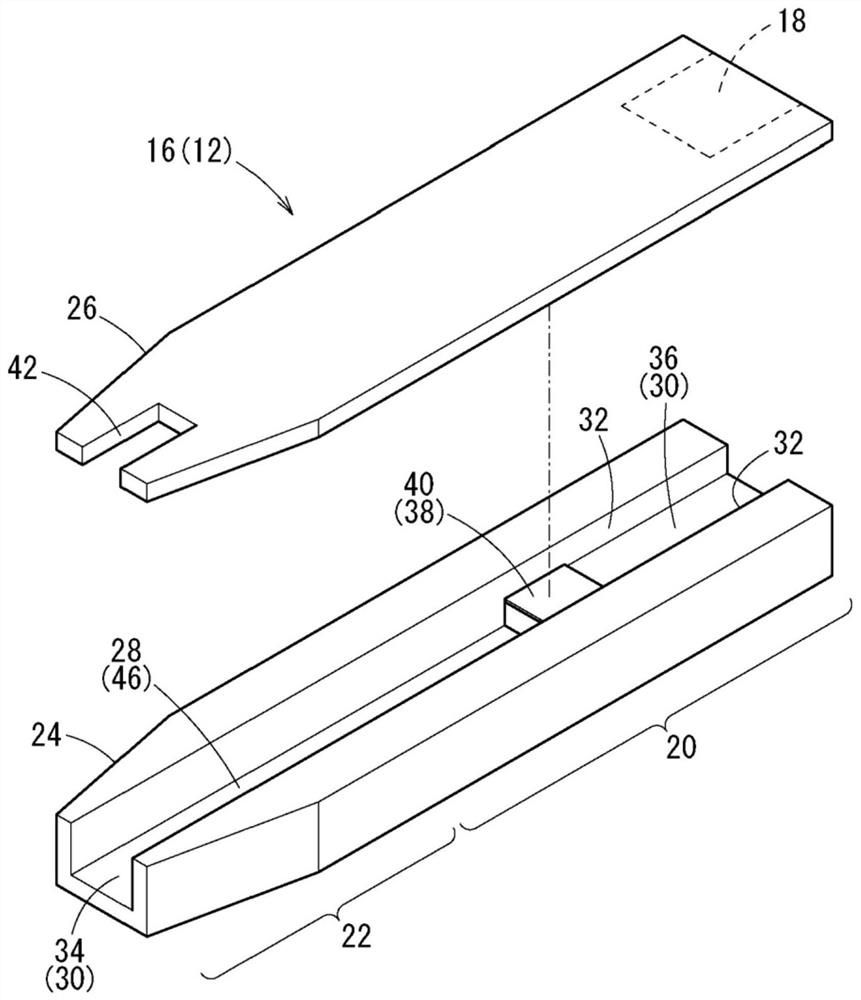
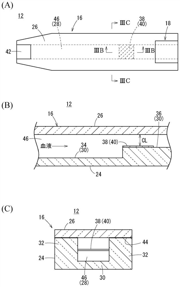
[0038] Such as figure 2 , image 3 (A)~ image 3 As shown in (C), the measurement chip 12 of the blood glucose meter 10 has...
no. 2 Embodiment approach 〕
[0107] Next, refer to Figure 11 (A) and Figure 11 (B) describes the component measurement system 10A (blood glucose meter 10A) according to the second embodiment. In addition, in the following description, the same code|symbol is attached|subjected to the element which has the same structure or the same function as the above-mentioned embodiment, and the detailed description is abbreviate|omitted.
[0108] The blood glucose meter 10A differs from the blood glucose meter 10 according to the first embodiment in that the printed layer 18A of the measurement chip 12A has a shape-changing pattern that can recognize information related to the space interval CL, and the measurement device 14 reads the pattern. And the space interval CL is obtained. In addition, the measurement device 14 has the same structure as the measurement device 14 according to the first embodiment (the detection unit 64, the control unit 88, etc.), and the control unit 88 is configured to analyze the patte...
no. 3 Embodiment approach 〕
[0115] Such as Figure 12 (A) and Figure 12 As shown in (B), the blood glucose meter 10B according to the third embodiment is different from the above-mentioned blood glucose meters 10 and 10A in that one of the plurality of light emitting elements 76 of the detection unit 64 is arranged closer to the other elements. The front end side serves as the reading unit 110 for detecting the printed layer 18B of the measurement chip 12B. In addition, the blood glucose meter 10B is configured to detect the printed layer 18B in a state where the measurement chip 12B is mounted on the measurement device 14B (mounting completion position).
[0116] The printed layer 18B of the measurement chip 12B is provided on the upper surface of the insertion range 20 on the front end side (the front side in the insertion direction) of the detection area 38 . For example, the printed layer 18B is positioned substantially in the middle in the longitudinal direction of the measurement chip 12B, and i...
PUM
 Abstract
Description
Claims
Application Information