Papermaking machine roll shaft joint device

A joint device and paper machine technology, applied in the field of mechanical parts, can solve problems such as failure of mechanical connection, influence on machining, and inability to effectively control the axial movement of the rotating shaft, so as to avoid axial movement and improve stability Effect

Inactive Publication Date: 2021-06-08
梁小洁
View PDF0 Cites 0 Cited by
  • Summary
  • Abstract
  • Description
  • Claims
  • Application Information

AI Technical Summary

Problems solved by technology

When the shaft moves axially, it is easy to cause the failure of the mechanical connection and affect the progress of machining
[0003] However, the existing paper machine roll joint device simply connects the two rotating shafts, does not provide an effective structure for axially positioning the rotating shafts, and cannot effectively control the axial movement of the rotating shafts

Method used


Image

  • Papermaking machine roll shaft joint device
  • Papermaking machine roll shaft joint device
  • Papermaking machine roll shaft joint device

Examples


Embodiment

[0099] The technical solutions of the various embodiments of the present invention will be clearly and completely described below in conjunction with the accompanying drawings. Apparently, the described embodiments are only some of the embodiments of the present invention, not all of them. Based on the embodiments described in the present invention, all other embodiments obtained by persons of ordinary skill in the art without creative efforts are within the protection scope of the present invention.

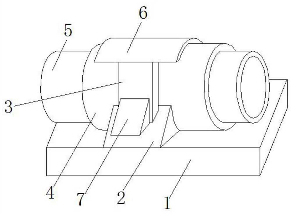
[0100] An embodiment of the present invention provides a paper machine roll shaft joint device, which can stably connect and position the paper machine roll shaft, and avoid large axial movement of the shaft.

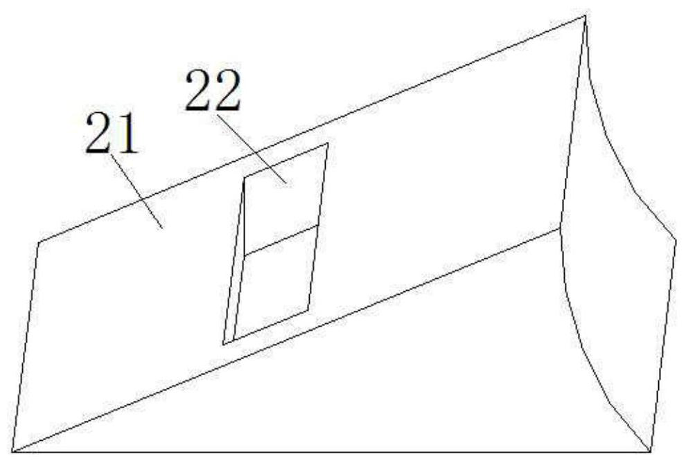
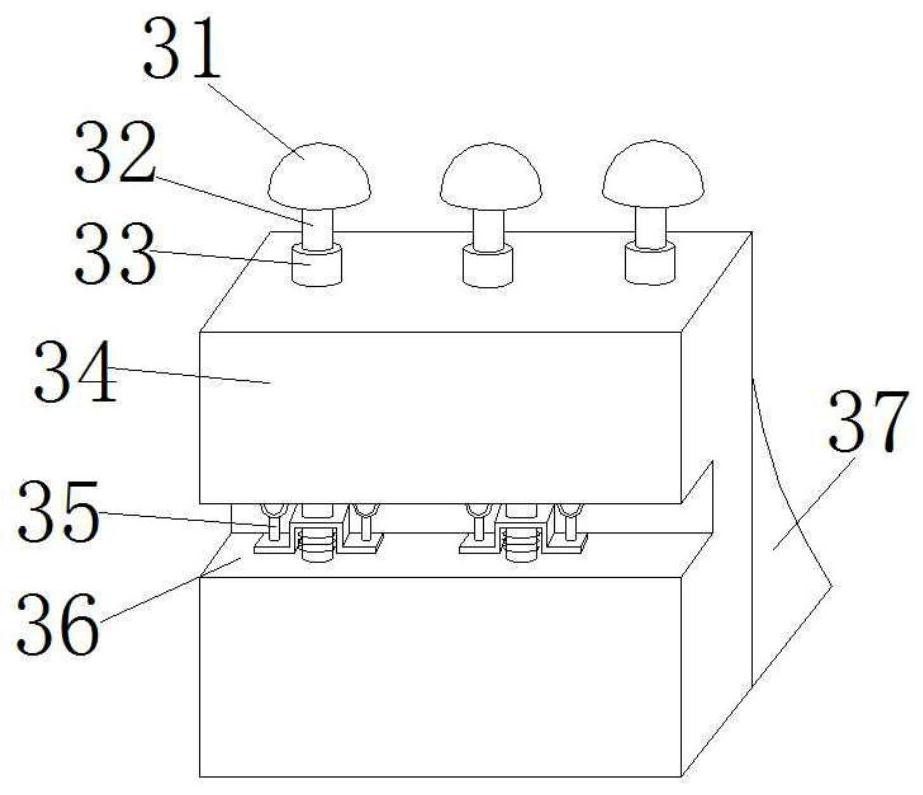
[0101] Such as Figure 1 to Figure 10 Shown:

[0102] The paper machine roll shaft joint device in this embodiment includes a rectangular bottom plate 1 and a fixing seat 2, which is fixed on two edges of the upper side of the bottom plate 1 with bolts. The connecting p...


PUM


Abstract

A papermaking machine roll shaft joint device comprises a bottom plate and further comprises fixing seats, and a connecting pipe is arranged between the two fixing seats. end fixing pieces are arranged at the two ends of the connecting pipe; a clamping piece is arranged on the upper side of the fixing seat and connected to the outer wall of the connecting pipe; an auxiliary fixing frame is arranged on the upper side of the fixing seat and connected to the side wall of the clamping piece; extrusion pieces are arranged at the upper ends of the two clamping pieces and are connected to the upper side of the connecting pipe; the end fixing piece comprises an outer jacking pipe, and a first protrusion is arranged at one end of the outer jacking pipe. the inner jacking pipe is arranged in an inner cavity of the outer jacking pipe; a first screw rod is screwed on the outer jacking pipe and the inner jacking pipe; a first extrusion block is convexly arranged on the outer wall of the other end of the outer jacking pipe; a second screw rod is screwed on the first extrusion block; a first adjusting seat is arranged on the second screw rod; a first end cover is arranged at the end part of the outer jacking pipe; a second buffer seat is arranged at the edge of the first end cover; and a joint device can axially position the roll shaft of the paper machine.

Description

technical field [0001] The invention relates to mechanical parts, in particular to a paper machine roll shaft joint device. Background technique [0002] The paper machine roll shaft joint device, as the name suggests, is to use the joint device to axially connect the paper machine roll shaft and other transmission shafts to transmit power. When the joint device is used to connect the two rotating shafts, due to the vibration in the longitudinal direction during the mechanical transmission process, the rotating shafts will also move in the axial direction at the same time. When there is axial movement of the rotating shaft, it is easy to cause mechanical connection failure and affect the progress of machining. [0003] However, the existing paper machine roll joint device simply connects two rotating shafts, does not provide an effective structure for axial positioning of the rotating shafts, and cannot effectively control the axial movement of the rotating shafts. [0004...

Claims


Application Information

Patent Timeline
Patent Type & Authority Applications(China)
IPC IPC(8): D21F7/00D21F7/02
CPCD21F7/00D21F7/02
Inventor 不公告发明人
Owner 梁小洁
Why Eureka
Try Eureka