Control valve and water heater circulating system

A technology for controlling valves and water heaters, which is applied in the field of valve structures, and can solve problems such as misstarting of water heaters 90, shortening the service life of water heaters 90, increasing user costs, and achieving the effect of avoiding false starts

Active Publication Date: 2021-06-08
NINGBO FOTILE KITCHEN WARE CO LTD
View PDF9 Cites 1 Cited by
  • Summary
  • Abstract
  • Description
  • Claims
  • Application Information

AI Technical Summary

Problems solved by technology

After receiving the water flow signal, the control device in the water heater 90 may think that hot water is needed, and then start the heating device 902 of the water heater 90, and the heating device 902 starts to heat the water, thus causing the water heater 90 to "wrongly start"
The "false start" of the water heater 90 will definitely cause waste of fuel or electric energy, increase the user's use cost, and also greatly shorten the service life of the water heater 90

Method used


Image

  • Control valve and water heater circulating system
  • Control valve and water heater circulating system
  • Control valve and water heater circulating system

Examples


Embodiment 1

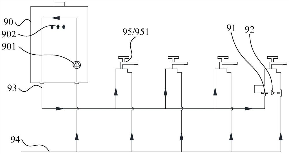
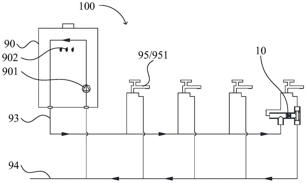
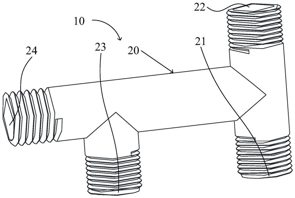
[0171] Such as Figure 2 to Figure 14 As shown, the present embodiment is a water heater circulation system 100, which includes a water heater 90, a hot water pipeline 93, a cold water pipeline 94 and several water terminals 95, and the water terminals 95 pass through the hot water pipeline 93 and the water outlet of the water heater 90. The cold water pipeline 94 communicates with the water inlet and the water end 95 of the water heater 90 respectively; the water heater circulation system 100 also includes a control valve 10 as follows, the cold water pipeline 94 communicates with the first communication port 21, and the second communication The port 22 communicates with the water port 95, and the third communicating port 23 communicates with the hot water pipe.

[0172] In the water heater circulation system 100 of this embodiment, by connecting the cold water pipeline 94 with the first communication port 21, the second communication port 22 with the water end 95, and the ho...

Embodiment 2

[0219] Such as Figure 16 As shown, this embodiment is basically the same as Embodiment 1, the difference is that the spool 30 of this embodiment is as Figure 16 shown. Such as Figure 16 Only the valve core 30 located in the valve body 20 and the first communication port 21 , the second communication port 22 and the third communication port 23 of the valve body 20 are shown, and other components are not shown.

[0220] exist Figure 16 Among them, the valve core 30 includes a blocking plate 421 , a driving plate 411 and a pivot shaft 31 . At least part of the blocking plate 421 is located in the flow space of the first fluid, and the blocking plate 421 is disposed close to the third communication port 23 . The blocking plate 421 and the driving plate 411 may be directly connected, and the pivot shaft 31 is located at the intersection of the blocking plate 421 and the driving plate 411 . Cold water can flow upward from the first communication port 21 to the second commun...

Embodiment 3

[0222] Such as Figure 17 As shown, this embodiment is basically the same as Embodiment 1, the difference is that the flow guiding part 50 of this embodiment is a partition 53, such as Figure 16 shown. Such as Figure 16 Only the valve core 30 located in the valve body 20 and the first communication port 21 , the second communication port 22 and the third communication port 23 of the valve body 20 are shown, and other components are not shown.

[0223] The guide part 50 is a partition 53, one side of the partition 53 and the corresponding inner surface of the valve body 20 form the first passage 25; the other side of the partition 53 and the corresponding inner surface of the valve body 20 form the first passage 25. The deflector 50 is configured as a partition 53, which has a simple structure and is convenient to form.


PUM


Abstract

The invention discloses a control valve and a water heater circulating system. The control valve comprises a valve body and a valve core, wherein the valve body is provided with a first communication port, a second communication port and a third communication port which are communicated; a fluid in the control valve flows from the first communication port to the second communication port to form a first fluid, and the first fluid acts on the valve element so that the valve element can be switched to be in a closed state; and when the valve core is in a closed state, the third communication port is blocked from the first communication port and the second communication port. The fluid in the control valve flows from the first communicating port to the second communicating port to form the first fluid, the first fluid acts on the valve element, the valve element can be switched to be in the closed state, and therefore the fluid is prevented from flowing into the first communicating port or the second communicating port through the third communicating port. According to the water heater circulating system using the control valve, hot water can be prevented from flowing into the first communicating port or the second communicating port through the third communicating port and flowing out of the water using end, and the problem that a user needs cold water and hot water flows out can be solved.

Description

technical field [0001] The invention relates to the field of valve structures, in particular to a control valve and a water heater circulation system Background technique [0002] With the continuous improvement of the quality of life, there are more and more zero-cold water heaters with circulation heating function. Such as figure 1 As shown, the common water heater 90 with zero cold water function and its waterway system are shown in the figure. At the water end 95 at the farthest end of the waterway in the family, use a three-way pipe 91 and a one-way valve 92 to connect the hot water pipeline 93 with the cold water pipeline 94, figure 1 The water end 95 is a faucet 951. [0003] When hot water is needed, just connect the faucet 951 to the direction of the hot water pipeline 93, and the hot water flows out from the hot water pipeline 93 through the faucet 951. The one-way valve 92 can effectively prevent the cold water in the cold water pipeline 94 from pouring back i...

Claims


Application Information

Patent Timeline
Patent Type & Authority Applications(China)
IPC IPC(8): F16K11/052F16K15/06
CPCF16K11/052F16K15/063
Inventor 宋一诺梁稳徐科杰周高云
Owner NINGBO FOTILE KITCHEN WARE CO LTD
Why Eureka
Try Eureka