In-pipe two-phase flow boiling heat transfer test system and control method thereof

A test system and boiling heat transfer technology, applied in the direction of material thermal development, etc., can solve the problems of reducing the saturation pressure adjustment range, complex structure, huge system, etc., to achieve good stability, simple operation, and high accuracy of parameter control. Effect

Pending Publication Date: 2021-06-08
浙大宁波理工学院
View PDF0 Cites 6 Cited by
  • Summary
  • Abstract
  • Description
  • Claims
  • Application Information

AI Technical Summary

Problems solved by technology

Based on the experimental debugging results, in addition to defects such as complex structure and large system, this system has relatively large limitations in the adjustment range of experimental working conditions: 1) The saturation pressure of flow boiling heat transfer is low, while the flow rate of working fluid, dryness, etc. The working conditions are all positively correlated with the saturation pressure. In order to meet the saturation pressure setting requirements, there will be greater capacity adjustment requirements for expansion valves, low-temperature cold sources and other equipment; 2) In the experimental section, water is used to heat the working fluid. The effective use range of the bypass valve is above 0°, which indirectly reduces the adjustment range of the saturation pressure; 3) When the flow rate of the working fluid is large, the pressure reduction effect of the bypass valve is lower than its flood discharge effect, that is, when the saturation pressure reaches the set value Under the working conditions, most of the working fluid flows to the liquid reservoir through the bypass valve, so that the working fluid flow does not increase with the increase of the pump frequency

Method used


Image

  • In-pipe two-phase flow boiling heat transfer test system and control method thereof
  • In-pipe two-phase flow boiling heat transfer test system and control method thereof
  • In-pipe two-phase flow boiling heat transfer test system and control method thereof

Examples


Embodiment Construction

[0020] The present invention will be further described below through specific embodiments, but the present invention is not limited to the following specific embodiments.

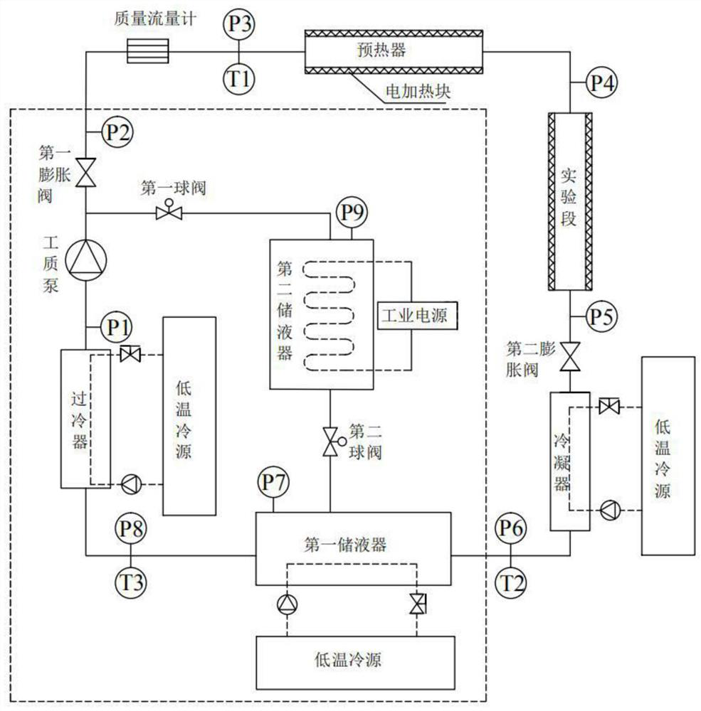
[0021] A two-phase flow boiling heat transfer test system in a tube, which generally includes a heat exchange tube test circuit and a working medium bypass circuit, specifically including a working medium pump, a first expansion valve, a mass flow meter, a preheater, an experimental section, a second Expansion valve, condenser, first liquid receiver, subcooler and second liquid receiver, including working medium pump, first expansion valve, mass flow meter, preheater, experimental section, second expansion valve, condenser , the first liquid receiver, and the subcooler are connected end to end in order to form a heat exchange tube test circuit; the second liquid receiver is connected to the pipeline between the first expansion valve and the working medium pump through the first ball valve, and passed through...


PUM


Abstract

The invention relates to the technical field of heat exchange testing, and concretely relates to an in-pipe two-phase flow boiling heat exchange testing system and a control method thereof. The test system sequentially comprises a working medium pump, a mass flow meter, a preheater, an experiment section, a second expansion valve, a condenser, a first liquid storage device and a subcooler, the first liquid storage device, the subcooler and the condenser are all connected with a low-temperature cold source, and the test system is characterized in that the first expansion valve is further arranged between the working medium pump and the mass flow meter, the test system further comprises a second liquid storage device, one end of the second liquid storage device is communicated with a pipeline between the working medium pump and the first expansion valve through a first ball valve, and the other end of the second liquid storage device is communicated with the first liquid storage device through a second ball valve. According to the scheme, the influence of the working medium flow fluctuation on the experimental parameter measurement precision can be effectively reduced, and the experimental test range can be expanded and the control precision of the working condition environment can be improved on the premise of the existing equipment component capability.

Description

technical field [0001] The invention relates to the technical field of heat transfer testing, in particular to a two-phase flow boiling heat transfer testing system in a tube and a control method. Background technique [0002] The research on the heat transfer characteristics of flow boiling of working fluid in various heat exchange tubes is one of the more important basic studies. The influence of structural parameters of heat exchange tubes and thermophysical properties of working fluid on the heat transfer characteristics of flow boiling in tubes is analyzed. The research and development of heat exchangers and the replacement of new refrigerants have guiding significance. [0003] Obtaining accurate experimental data of flow boiling heat transfer in tubes is a prerequisite for the study of its mechanism. Therefore, it is necessary to build a test platform to simulate the experimental operating environment, and then realize the research on the flow boiling heat transfer pr...

Claims


Application Information

Patent Timeline
Patent Type & Authority Applications(China)
IPC IPC(8): G01N25/20
CPCG01N25/20
Inventor 李庆普陈光明王勤高能黎念郝新月
Owner 浙大宁波理工学院
Why Eureka
Try Eureka