
Optical lens mounting device of laser collimator

A technology of optical lens and installation device, which is applied in the direction of installation, optics, optical components, etc. It can solve the problems of pollution affecting adhesion and inconvenient adjustment, and achieve the effect of avoiding long-term contact and avoiding deviation of dispensing

Active Publication Date: 2021-06-08
佛山市顺德区蚬华多媒体制品有限公司
View PDF3 Cites 0 Cited by
  • Summary
  • Abstract
  • Description
  • Claims
  • Application Information

AI Technical Summary

Problems solved by technology

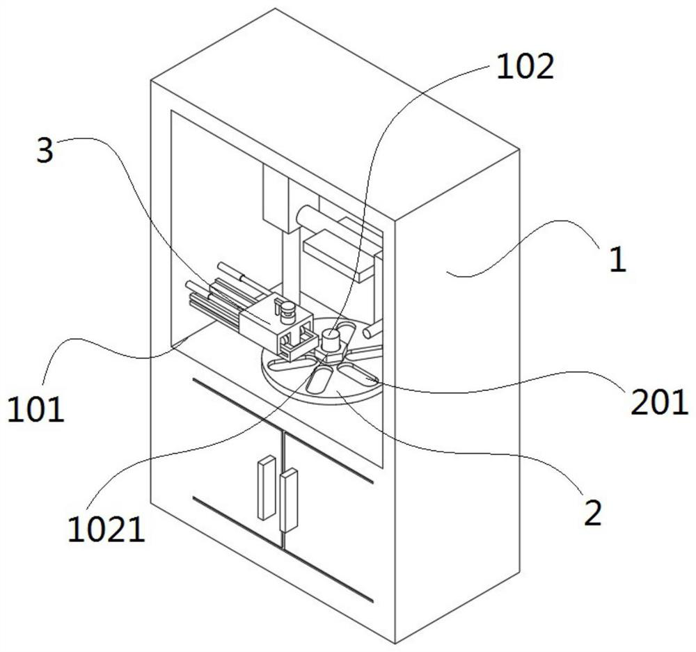
[0003] The object of the present invention is to provide an optical lens installation device for a laser collimator, which solves the problem of manual dispensing of the optical lens in the existing laser collimator. The adhesion of UV glue is affected by air pollution, as well as the problem of inconvenient adjustment of dispensing position and ultraviolet light curing UV glue process

Method used


Image

  • Optical lens mounting device of laser collimator
  • Optical lens mounting device of laser collimator
  • Optical lens mounting device of laser collimator

Examples


Embodiment Construction

[0027] The following will clearly and completely describe the technical solutions in the embodiments of the present invention with reference to the accompanying drawings in the embodiments of the present invention. Obviously, the described embodiments are only some, not all, embodiments of the present invention. Based on the embodiments of the present invention, all other embodiments obtained by persons of ordinary skill in the art without creative efforts fall within the protection scope of the present invention.

[0028] In the description of the present invention, it should be understood that the terms "upper", "middle", "outer", "inner" and the like indicate orientation or positional relationship, and are only for the convenience of describing the present invention and simplifying the description, rather than indicating or It should not be construed as limiting the invention by implying that a referenced component or element must have a particular orientation, be constructe...


PUM


Abstract

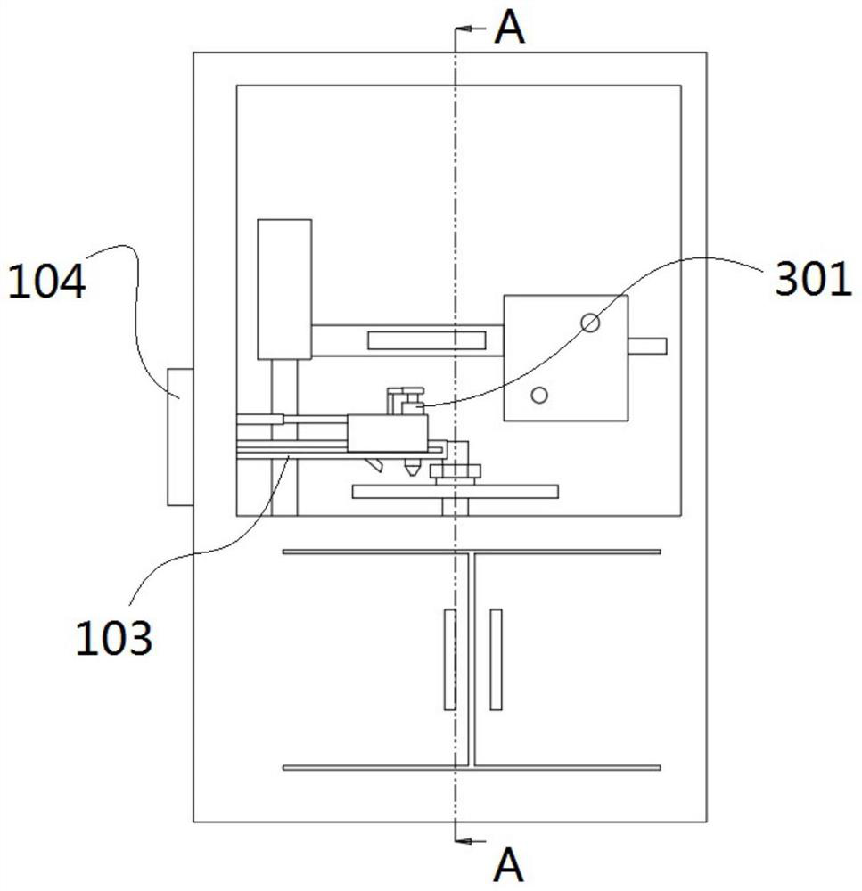
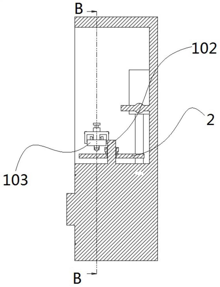
The invention discloses an optical lens mounting device of a laser collimator, and relates to the technical field of optical system adjustment. The device comprises a workbench, a mounting disc and a glue dispensing box, the glue dispensing box corresponds to the mounting disc in position, an exhaust fan is arranged in the glue dispensing box and corresponds to a glue dispensing head in position, and a speed regulator is arranged in the glue dispensing box and controls the wind power of the exhaust fan. By arranging the mounting disc and utilizing a mounting groove, a to-be-dispensed workpiece can be fixedly mounted conveniently, meanwhile, the mounting height of the workpiece is adjusted by utilizing a fastening bolt cap and a supporting spring, so that the workpiece adapts to the height position of a dispensing head, and long-time contact between UV glue and air is further avoided; and on the other hand, by arranging the exhaust fan and an exhaust pipe corresponding to the position of the dispensing head, starting of the exhaust fan is controlled through the glue pressing and dispensing action, meanwhile, the wind power is gradually reduced in the downward pressing process, air between the dispensing head and the workpiece can be exhausted, and dispensing deviation caused by too large wind power can be avoided.

Description

technical field [0001] The invention belongs to the technical field of optical detection instruments, in particular to an optical lens installation device of a laser collimator. Background technique [0002] In the field of laser print head manufacturing, it is necessary to adjust the optical path of the laser system. Some precise optical experimental instruments are often used, such as a laser collimator used to correct the collimation of the light source; during the use of the laser collimator, it is necessary to adjust Optics The relative position of the optical lens and the laser device to achieve the desired spot shape. Therefore, in order to realize the spot fixation, it is necessary to design a set of optical lens installation and fixing unit in the laser collimation adjustment system to realize fast fixation of the spot after adjustment. The traditional optical lens is installed and fixed manually, which takes a long time and is easy to cause vibration and micro-dis...

Claims


Application Information

Patent Timeline
Patent Type & Authority Applications(China)
IPC IPC(8): G02B7/02G02B27/30
CPCG02B7/025G02B27/30
Inventor 邓自然黄宇传王书方
Owner 佛山市顺德区蚬华多媒体制品有限公司
Learn More