Light mixing module, display device adopting light mixing module, and design method of light mixing module

A module and light mixing technology, which is applied in identification devices, optics, light guides, etc., can solve the problem of uneven brightness of the light-emitting surface of the light mixing module, and achieve the effect of improving the dynamic display range, improving the display effect, and improving the manufacturing efficiency.

Pending Publication Date: 2021-06-08
HAIDIKE NANTONG OPTOELECTRONICS TECH CO LTD
View PDF0 Cites 2 Cited by
  • Summary
  • Abstract
  • Description
  • Claims
  • Application Information

AI Technical Summary

Problems solved by technology

[0005] The technical problem to be solved by the present invention is to provide a light mixing module with a reflective structure, which uses reflected light to compensate the dark area of ​​the backlight module, and can solve the technical problem of uneven brightness on the light output surface of the light mixing module. Display device using the light mixing module and design method of the light mixing module

Method used


Image

  • Light mixing module, display device adopting light mixing module, and design method of light mixing module
  • Light mixing module, display device adopting light mixing module, and design method of light mixing module
  • Light mixing module, display device adopting light mixing module, and design method of light mixing module

Examples


Embodiment 1

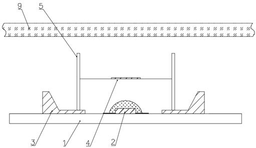
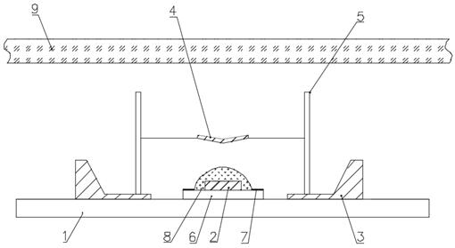
[0084] In this example, if figure 2 As shown, the LED chip 2 is indirectly mounted on the main substrate 1, specifically, the LED chip 2 is mounted on a sub-substrate 6, the sub-substrate 6 is mounted on the main substrate 1, and the sub-substrate 6 on the periphery of the LED chip 2 The surface is coated with a lower reflective layer 7, which is used to reflect the light incident on the substrate to the side of the light-emitting surface, so as to achieve the effect of mixing and filling light, and improve the utilization rate of light. In this embodiment, the width of the lower reflection layer is 0.5-1.5 mm. The LED chip 2 can be covered with an encapsulation layer 8, and the encapsulation layer 8 is arranged on the top and side walls of the LED chip to form a spherical package. The encapsulation layer 8 forms a spherical or rectangular transparent glue by means of molding and dispensing, which is conducive to the emission of light and facilitates more uniform mixing of l...

Embodiment 2

[0094] The structure of this embodiment is basically the same as that of Embodiment 1, including a main substrate 1 with a printed circuit, and at least one chip-level light-emitting unit arranged on the main substrate 1. The chip-level light-emitting unit includes an LED chip 2, a backlight bracket 3, and a light-shielding unit. The element 4 and the support element 5 have the same connection relationship, and the LED chip 2 is also covered with an encapsulation layer 8, the difference is that:

[0095] In this embodiment, the LED chip 2 is an RGB three-primary color chip, and the three three-primary color chips 21, 22, and 23 are jointly coated in the encapsulation layer 8, and the encapsulation layer 8 is preferably a transparent adhesive layer, that is, multiple LED chips are packaged The light source packaging unit formed after being put together.

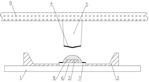
[0096] In this example, D Z with D X The relationship satisfies the following conditions: D X Z X +2H Z *tan30°, and H ...

Embodiment 3

[0108] The present invention provides a method for quickly designing the light mixing module of the present invention, the steps of which are: 1.

[0109] S1: Determine the maximum value of DHR that the light mixing module needs to achieve: DHR MAX ;

[0110] S2: Select the LED chip specification of the chip-level light-emitting unit;

[0111] S3: Select the appropriate shading element specification for the chip-level light-emitting unit:

[0112] D. Z with D X The relationship satisfies the following conditions: D X Z X +2H Z *tan30°, and H Z 0.2 ~ 1mm, D X is the overall size of the LED chip and its encapsulation layer, H Z The distance between the lower surface of the shading element and the bottom surface of the LED chip, D Z is the width of the shading element in the horizontal direction;

[0113] got a D Z 、H Z size range;

[0114] S4: Calculate the specification parameters of the cup-shaped reflective surface of the backlight bracket:

[0115] S4.1: Fir...


PUM

PropertyMeasurementUnit
widthaaaaaaaaaa
thicknessaaaaaaaaaa
thicknessaaaaaaaaaa

Abstract

The invention relates to a light mixing module, a display device adopting the light mixing module and a design method of the light mixing module. The light mixing module is characterized in that the light mixing module comprises a main substrate with a printed circuit and at least one chip-level light-emitting unit arranged on the main substrate, the chip-level light-emitting unit comprises an LED chip, a backlight support, a shading element and a supporting element, and the backlight support is mounted on the main substrate and is provided with a cup-shaped reflecting surface surrounding the periphery of the LED chip; and the shading element is suspended right above the LED chip through the supporting element. The light mixing module has the advantages that the cup-shaped reflecting surface reflects the light rays directly emitted by the chip and reflected by the shading element to the area to be supplemented with light, the problem that the brightness of the light emitting layer of the light mixing module is not uniform is solved, the loss of reflected light is avoided, and the brightness and the overall display effect are improved.

Description

technical field [0001] The invention relates to a light mixing module and a display device thereof, and also relates to a design method of the light mixing module. Background technique [0002] There is no essential difference between Mini LED backlight and LED. It is a backlight technology, and the size of a single LED is greatly reduced. Usually, when used as a light mixing module, the LEDs are packaged on the PCB and arranged in a matrix. Since the number of LEDs is far greater than the number of CCFLs, each LED can be used as an independent light source to form a dynamic partition backlight, improve the dynamic contrast of the display device, and realize HDR display. After the size is reduced, more LED lights are required to form a Mini LED mixing light module, and there will be more dynamic partitions, which can be easily manufactured into curved surfaces. In terms of technical principles, the Mini LED backlight is actually an upgrade of the LED backlight. Originally,...

Claims


Application Information

Patent Timeline
Patent Type & Authority Applications(China)
IPC IPC(8): H01L33/60H01L33/00G09F9/33
CPCH01L33/60G09F9/33H01L33/005H01L2933/0058G02F1/133606G02F1/133603G02F1/133605G02B6/0055G02B6/0068G02B6/0073G02B6/0081
Inventor 孙智江王书昶沈阳
Owner HAIDIKE NANTONG OPTOELECTRONICS TECH CO LTD
Why Eureka
Try Eureka