Cable and wire core wiring method thereof

A wiring method and cable technology, applied in the direction of circuits, connections, electrical components, etc., can solve problems such as improper cooperation between the crimping die and the surface of the connecting pipe, breakdown, and puncture of the cable insulator

Pending Publication Date: 2021-06-08
ELECTRIC POWER RES INST OF GUANGDONG POWER GRID
View PDF2 Cites 1 Cited by
  • Summary
  • Abstract
  • Description
  • Claims
  • Application Information

AI Technical Summary

Problems solved by technology

[0004] However, when using the above-mentioned crimping method to carry out the wiring operation on the cable core, due to improper cooperation between the crimping die and the surface of the connecting pipe, it is easy to cause the risk of the cable insulator being punctured or broken down.

Method used


Image

  • Cable and wire core wiring method thereof
  • Cable and wire core wiring method thereof
  • Cable and wire core wiring method thereof

Examples


Embodiment 1

[0040] refer to Figure 6 As shown, the present invention provides a cable core 200 wiring method, the method includes the following steps:

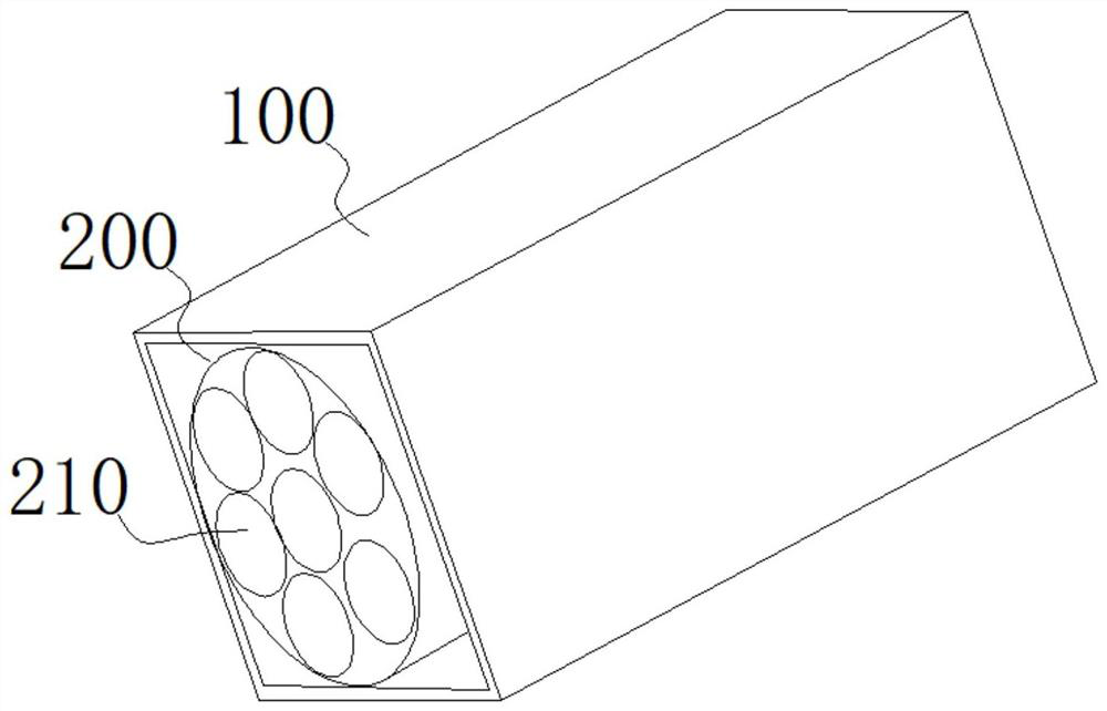
[0041] Step S110 : Insert the cores 200 of the two cables into the connecting tube 100 . Wherein, the connecting pipe 100 is made of metal, and its cross section is polygonal.

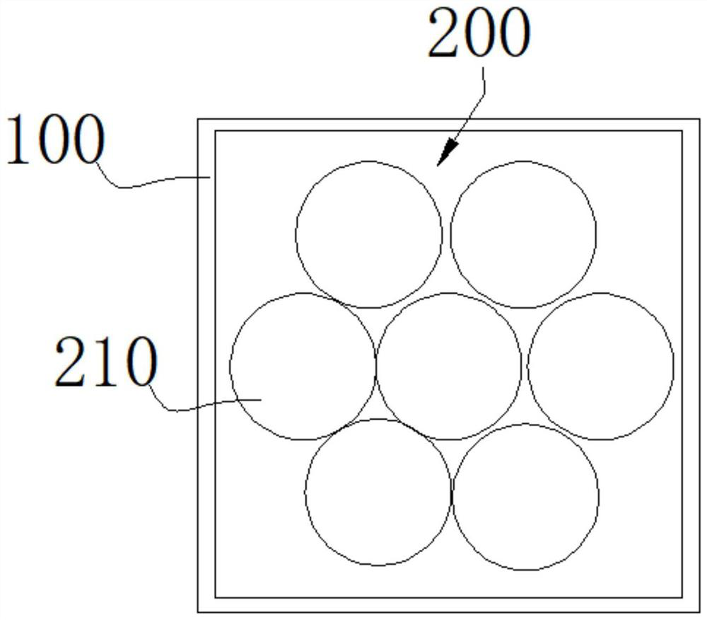
[0042] Such as figure 1 and figure 2 As shown, in this example, the connecting pipe 100 is a quadrangular metal pipe. Strip off the cable insulators at the ends of the two cables to expose the cable core 200, such as figure 2 As shown, a bundle of cable cores 200 is formed by winding seven wires 210, and the seven wires 210 can be misaligned (that is, can move relative to each other) when subjected to external extrusion.

[0043] Step S120: Use the crimping die 400 to press the connecting tube 100 radially from the outside to the inside, so that the connecting tube 100 is interference-fitted with the cores 200 of the two cables. Among them, such as Figu...

Embodiment 2

[0049] refer to Figure 7 As shown, the present invention provides a cable core 200 wiring method, the method includes the following steps:

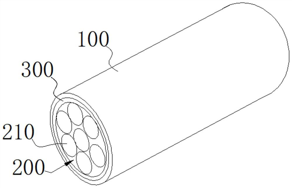
[0050] Step S210: inserting the embedded liner 300 into the connecting pipe 100; wherein, both the embedded liner 300 and the connecting pipe 100 are made of metal, and the cross section of the connecting pipe 100 is quadrilateral.

[0051] Step S220 : Insert the wire cores 200 of the two cables into the embedded liner 300 .

[0052] Step S230 : Use the crimping die 400 to press the connecting pipe 100 from outside to inside in the radial direction, so that the connecting pipe 100 is interference-fitted with the core 200 of the two-section cable and the embedded liner 300 . Among them, such as Figure 5 As shown, the crimping die 400 includes an upper die 410 and a lower die 420, and the upper die 410 and the lower die 420 can move up and down driven by a hydraulic mechanism. The lower end surface of the upper mold 410 has a first cri...


PUM


Abstract

The invention discloses a cable and a wire core wiring method thereof. The method comprises the following steps of: inserting wire cores of two sections of cables into a connecting pipe; wherein the connecting pipe is made of a metal material, and the section of the connecting pipe is polygonal; extruding the connecting pipe from outside to inside along the radial direction by using a crimping die so as to enable the connecting pipe to be in interference fit with the wire cores of the two sections of cables; wherein the crimping die comprises an upper die and a lower die, the upper die is provided with a first crimping surface with a downward opening, the lower die is provided with a second crimping surface with an upward opening, the first crimping surface and the second crimping surface are arc-shaped, and the first crimping surface and the second crimping surface are used for jointly extruding the connecting pipe. As the surface of the crimping die is in the smooth arc shape, burrs and pressing pits with large deformation on the outer surface of the connecting pipe can be reduced during crimping, so that the risk of cutting a cable insulator and the risk of puncturing the cable insulator are avoided.

Description

technical field [0001] The invention relates to the technical field of cables, in particular to a cable and a wire core connection method thereof. Background technique [0002] Power cable accessories are products that connect cables with power transmission and distribution lines and related power distribution devices. Generally, they refer to the intermediate connections and terminal connections of various cables in cable lines. They form a power transmission network together with cables; cable accessories are mainly based on cable structures. It can not only restore the performance of the cable, but also ensure the extension of the cable length and the connection of the terminal. [0003] The connecting tube used to connect two cables is a part of the cable accessories. In related technologies, the crimping method is generally used to realize the connection of two cables. The operation is: first insert the cores of the two cables into the connecting tube, and then Use hyd...

Claims


Application Information

Patent Timeline
Patent Type & Authority Applications(China)
IPC IPC(8): H01R43/042H01R4/20
CPCH01R43/042H01R4/20
Inventor 汪进锋姚瑶金杨彭向阳李鑫陈鹏
Owner ELECTRIC POWER RES INST OF GUANGDONG POWER GRID
Why Eureka
Try Eureka