Heating structure and atomizer

A technology for atomizers and heating elements, which is applied in the direction of tobacco, etc., can solve the problems of sticky core and uneven temperature of heating structure, and achieve the effect of avoiding burnt core and uniform temperature

Pending Publication Date: 2021-06-11
SHENZHEN GEEKVAPE TECH CO LTD
View PDF8 Cites 0 Cited by
  • Summary
  • Abstract
  • Description
  • Claims
  • Application Information

AI Technical Summary

Problems solved by technology

[0003] In the existing technology, metal meshes are often used in series to heat the e-liquid. The metal meshes in series are affected by the metal meshes on both sides due to the heat dissipation in the middle, and the temperature is relatively high. As a result, when the heating structure is working, the middle temperature is high, and the temperature on both sides is low. When the structure is working, the temperature is not uniform, and even the phenomenon of core burnt occurs

Method used


Image

  • Heating structure and atomizer
  • Heating structure and atomizer
  • Heating structure and atomizer

Examples


Embodiment 1

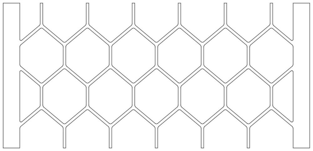
[0041] The heating element 20 is made of nickel-chromium alloy (Cr20Ni80), the thermal conductivity is 60.3W / (m c), the resistivity is 1.09E-06Ω.m, the shape of the heating unit is hexagonal, the total length of the heating structure is 12mm, and the total width 5.7mm, thickness 0.1mm.

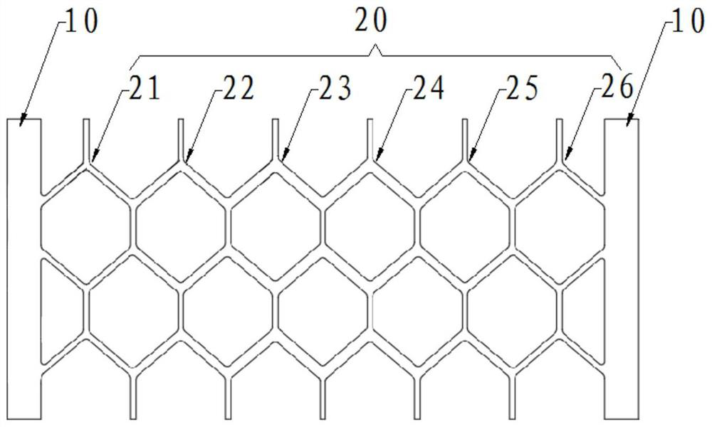
[0042] see figure 2 The wire width of the first heating unit 21 and the sixth heating unit 26 is 0.1 mm, the wire width of the second heating unit 22 and the fifth heating unit 25 is 0.2 mm, and the wire width of the third heating unit 23 and the fourth heating unit 24 The width is 0.25mm.

[0043] After testing, the temperature at the first heating unit 21 and the sixth heating unit 26 is 280°C, the temperature at the second heating unit 22 and the fifth heating unit 25 is 285°C, the third heating unit 23 and the fourth heating unit 24 The temperature at 281°C is basically the same.

Embodiment 2

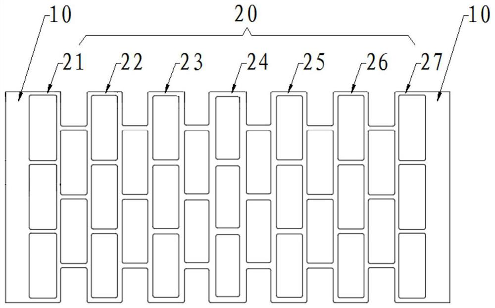
[0045] The heating element 20 is made of nickel-chromium alloy (Cr20Ni80), the thermal conductivity is 60.3W / (m c), the resistivity is 1.09E-06Ω.m, the shape of the heating unit is rectangular, the total length of the heating structure is 12mm, and the total width is 5.7mm , thickness 0.1mm.

[0046] see image 3The wire width of the first heating unit 21 and the seventh heating unit 27 is 0.1 mm, the wire width of the second heating unit 22 and the sixth heating unit 26 is 0.15 mm, and the wire width of the third heating unit 23 and the fifth heating unit 25 The width is 0.2 mm, and the wire width of the fourth heating unit 24 is 0.25 mm.

Embodiment 3

[0048] The heating element 20 is made of nickel-chromium alloy (Cr20Ni80), the thermal conductivity is 60.3W / (m c), the resistivity is 1.09E-06Ω.m, the shape of the heating unit is rhombus, the total length of the heating structure is 12mm, and the total width is 5.7mm , thickness 0.1mm.

[0049] see Figure 4 The wire width of the first heating unit 21 and the sixth heating unit 26 is 0.1 mm, the wire width of the second heating unit 22 and the fifth heating unit 25 is 0.15 mm, and the wire width of the third heating unit 23 and the fourth heating unit 24 The width is 0.2 mm.


PUM


Abstract

The invention provides a heating structure and an atomizer. The heating structure comprises pin wires and a heating piece, and the two ends of the heating piece are each connected with one pin wire; and the heating piece comprises at least three heating units, the heating units are connected in series, the areas of the cross sections of the heating units are gradually reduced from the center of the heating piece to the position of the pin wire, and the heating units are symmetrically arranged. The cross sections of the heating units are gradually reduced from the center of the heating piece to the position of the pin wire, the currents on the multiple heating units connected in series are the same, the cross section of the heating unit close to the middle is large, and the resistance value is low, so that the heating value of the heating unit close to the middle is smaller than that of the heating units on the two sides, at the moment, the temperature of the heating unit in the middle is reduced, and the temperature of the heating units on two sides rises. In combination with the heat dissipation condition of the heating piece, the temperatures of the middle part and the two sides of the heating piece can be kept relatively uniform, and the phenomenon of core pasting caused by overhigh temperature of the heating unit in the middle is avoided.

Description

technical field [0001] The invention relates to the technical field of atomization heating, in particular to a heating structure and an atomizer. Background technique [0002] The atomizer is powered by a battery rod, which can convert the liquid nicotine in the pod into mist, so that the user has a smoking-like feeling when inhaling. The core component of the atomizer is the heating structure, which is used to heat and atomize the e-liquid to meet the function of use. [0003] In the existing technology, metal meshes are often used in series to heat the e-liquid. The metal meshes in series are affected by the metal meshes on both sides due to the heat dissipation in the middle, and the temperature is relatively high. As a result, when the heating structure is working, the middle temperature is high, and the temperature on both sides is low. When the structure is working, the temperature is not uniform, and even the core phenomenon appears. [0004] Therefore, there is an ...

Claims


Application Information

Patent Timeline
IPC IPC(8): A24F40/10A24F40/40A24F40/46A24F40/57
CPCA24F40/10A24F40/40A24F40/46A24F40/57
Inventor 赖鸿好臧佳栋
Owner SHENZHEN GEEKVAPE TECH CO LTD
Why Eureka
Try Eureka