Pelvic floor muscle postoperative rehabilitation device
A rehabilitation device and pelvic floor muscle technology, applied in sports accessories, space-saving games, gymnastics equipment, etc., can solve problems such as urinary incontinence, and achieve the effect of a wide range of applications
- Summary
- Abstract
- Description
- Claims
- Application Information
AI Technical Summary
Problems solved by technology
Method used
Image
Examples
Embodiment 1
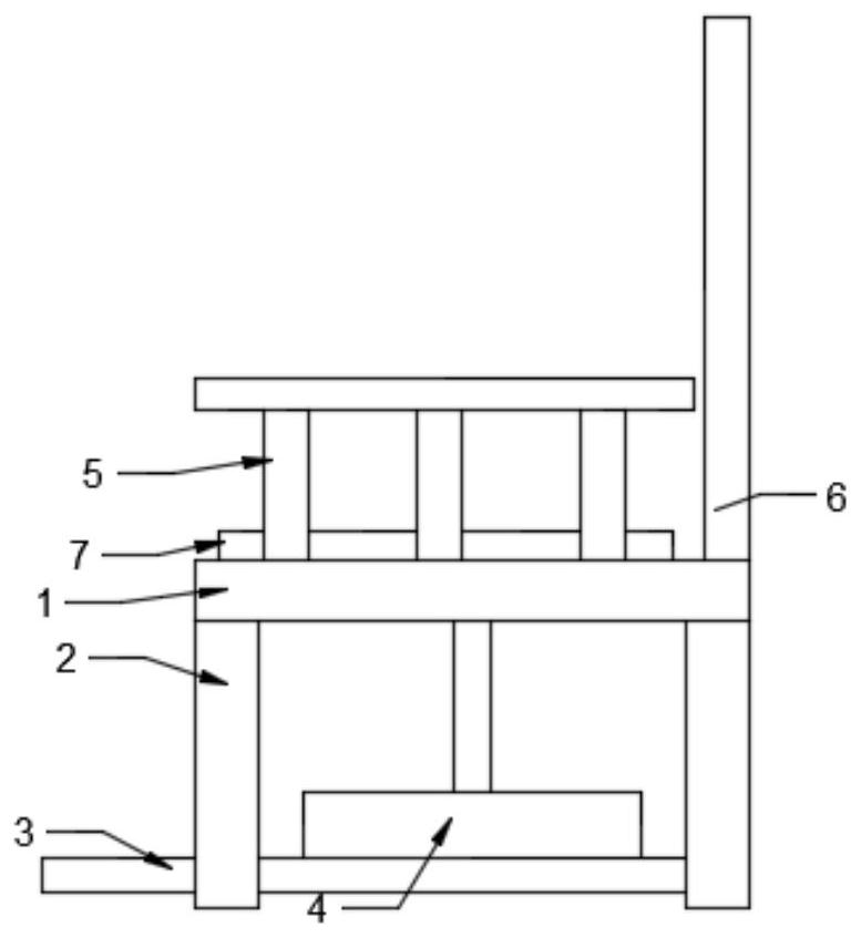
[0026] see Figure 1-7 , in an embodiment of the present invention, a postoperative rehabilitation device for pelvic floor muscles, comprising: a seat board 1, the lower part of the seat board 1 is fixedly equipped with outriggers 2, and a lower floor board 3 is arranged between the outriggers 2, so that A rotating mechanism 4 is fixedly installed on the lower bottom plate 3, handrails 5 are fixedly installed on both sides of the upper part of the seat plate 1, a backing plate 6 is fixedly installed on one side of the seat plate 1, and an adjusting mechanism is connected to the upper part of the rotating mechanism 4 7. The adjustment mechanism 7 is fixedly installed on the upper part of the seat plate 1 .
Embodiment 2
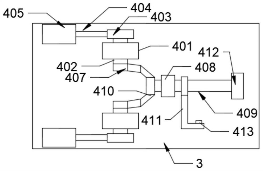
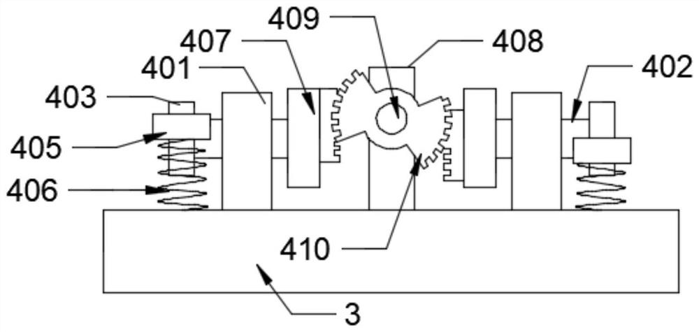
[0028] see Figure 1-7 , in this embodiment, the rotating mechanism 4 includes: a first fixed block 401, a first rotating rod 402 runs through the first fixed block 401, and a first rotating connection is fixedly installed at one end of the first rotating rod 402. Block 403, one side of the first rotating connecting block 403 is connected with a first connecting rod 404, the other end of the first connecting rod 404 is fixedly installed with a pedal 405, and the other end of the first rotating rod 402 is installed with a first A complete bevel gear 407, a second fixed block 408 is fixedly installed on the lower bottom plate 3, a second rotating rod 409 runs through the second fixed block 408, and a second incomplete Bevel gear 410, the first incomplete bevel gear 407 keeps meshing with the second incomplete bevel gear 410, the other end of the second rotating rod 409 is provided with a third fixed block 412, and the second rotating rod 409 is rotatably installed At the bottom...
Embodiment 3
[0031] see Figure 1-7, in this embodiment, the adjustment mechanism 7 includes: an upper base plate 701, the upper base plate 701 is fixedly installed on the upper part of the seat plate 1, a hydraulic cylinder 702 is fixedly installed on the upper base plate 701, and a hydraulic cylinder 702 is installed on the hydraulic cylinder 702. Hydraulic rod 703, the end of the hydraulic rod 703 is rotated with a first rod 704, the middle of the first rod 704 is rotated with a second rod 705; the third rotating rod 418 runs through the other side of the upper bottom plate 701 The side is provided with a rotating base 706, the third rotating rod 418 runs through the other end of the rotating base 418 and is connected with a first bevel gear 707, and one side of the first bevel gear 707 is meshed with a second bevel gear 710, and the rotating base 706 The upper side is fixedly connected with a slideway plate 708, the upper part of the slideway plate 708 is fixedly installed with a first...
PUM
 Abstract
Description
Claims
Application Information
 - R&D
- Intellectual Property
- Life Sciences
- Materials
- Tech Scout
- Unparalleled Data Quality
- Higher Quality Content
- 60% Fewer Hallucinations
Browse by: Latest US Patents, China's latest patents, Technical Efficacy Thesaurus, Application Domain, Technology Topic, Popular Technical Reports.
© 2025 PatSnap. All rights reserved.Legal|Privacy policy|Modern Slavery Act Transparency Statement|Sitemap|About US| Contact US: help@patsnap.com


