
Clothes dryer

A drying machine and clothing technology, which is used in household dryers, washing devices, textiles and paper making, etc., can solve the problems of shortening drying time, increasing wind speed, and increasing the amount of accumulation in the drainage tank.

Pending Publication Date: 2021-06-11
TOSHIBA LIFESTYLE PROD & SERVICES CORP
View PDF12 Cites 0 Cited by
  • Summary
  • Abstract
  • Description
  • Claims
  • Application Information

AI Technical Summary

Problems solved by technology

However, if the air volume is increased in this way to shorten the drying time, the amount of dripping water generated per unit time will increase, the amount of water accumulated in the drain tank will increase, and the wind speed will increase.
Therefore, the following disadvantages may occur: the dripping water accumulated in the drain tank is likely to be lifted by the wind blowing into the drain tank, carried by the wind and flow in the circulating air path, and then adhere to the clothes in the drum.

Method used


Image

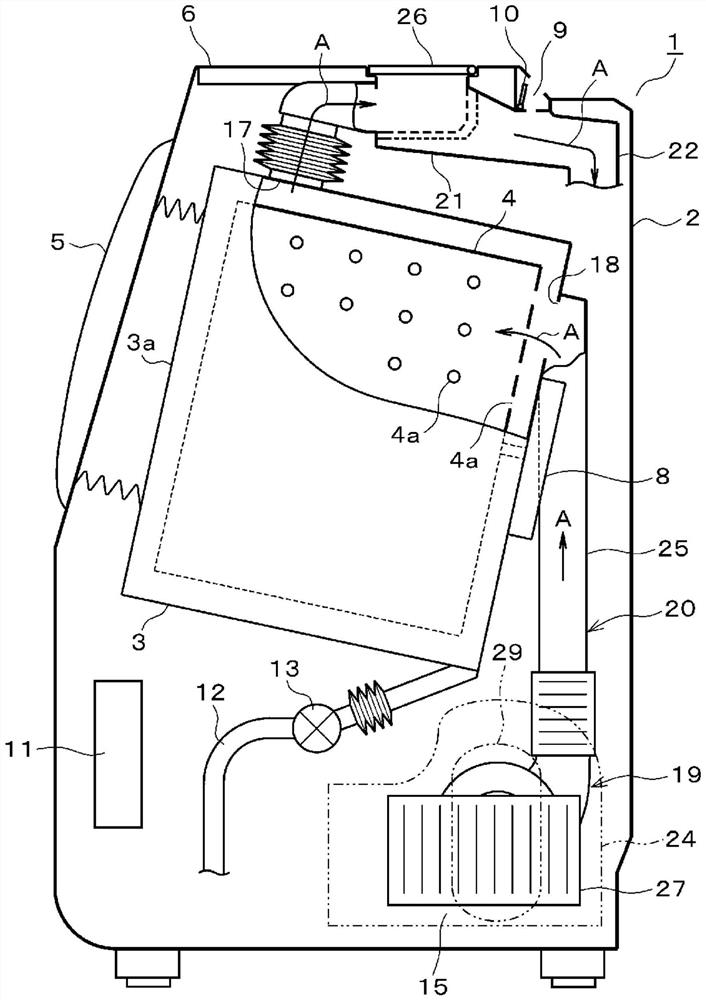
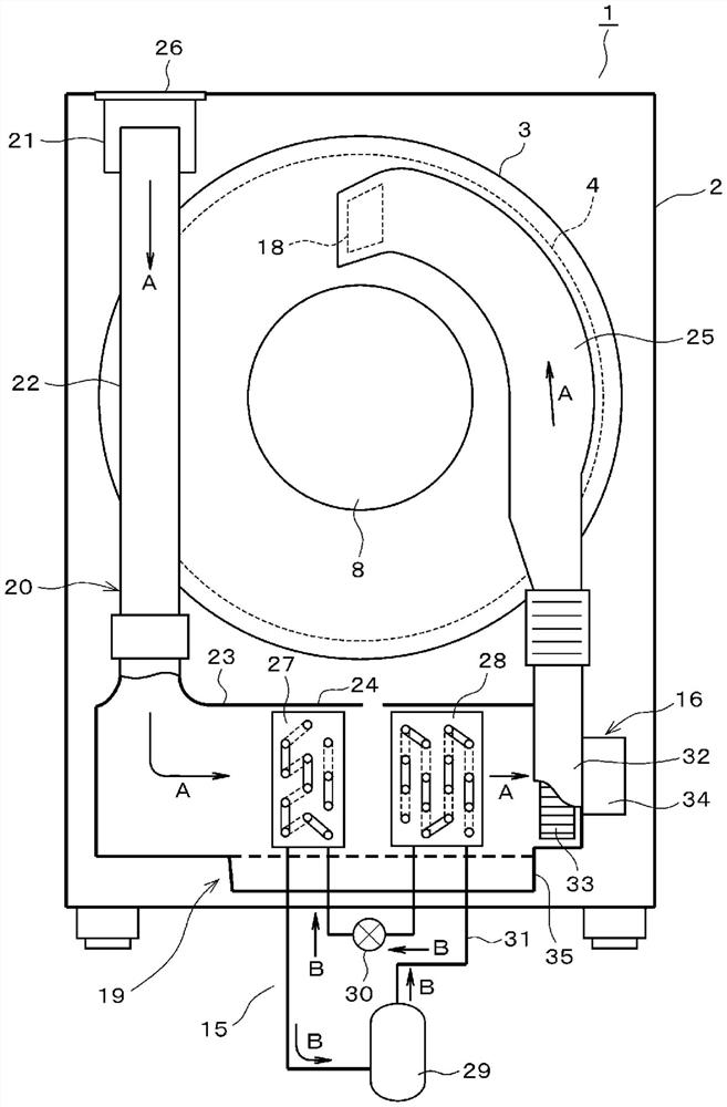
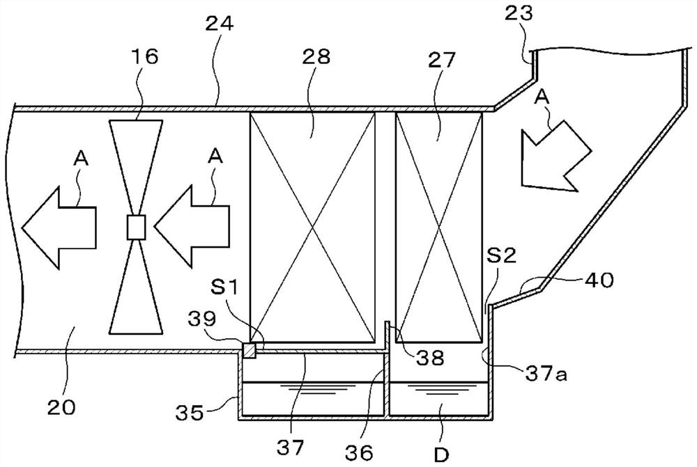
  • Clothes dryer
  • Clothes dryer
  • Clothes dryer

Examples


no. 2 Embodiment approach

[0055] Figure 4 The second embodiment was shown, and the difference from the above-mentioned first embodiment lies in the configuration of the wind direction plate 42 provided in the evaporator inlet duct 41 constituting a part of the circulation air passage 20 . That is, the evaporator inlet pipe 41 has a quadrangular pipe shape in cross section, and its front end, that is, the left end in the figure extends obliquely downward from the right in the figure, and is connected to the base end of the heat pump pipe 24, that is, the right end in the figure. . At this time, the lower side of the evaporator inlet pipe 41 is connected to the lower side of the heat pump pipe 24 by butting.

[0056] In addition, in the second embodiment, a separate wind direction plate 42 is attached to the bottom wall portion of the front end portion of the evaporator inlet duct 41 to direct the airflow upward. The wind direction plate 42 has a V-shaped cross section and is provided over the entire ...

no. 3 Embodiment approach

[0059] Figure 5 The third embodiment was shown, and the point of difference from the above-mentioned first embodiment is the configuration of the evaporator inlet duct 51 constituting a part of the circulating air duct 20 . That is, the front end portion (left end portion in the drawing) of the evaporator inlet pipe 51 has a rectangular pipe shape in cross section, extends horizontally, and is connected to the heat pump pipe 24 . In this way, the front end portion of the evaporator inlet duct 51 is close to the inlet of the evaporator 27 , and the wind enters the evaporator 27 at a right angle. In addition, the drain tank 35, the tank cover 37, the closing member 39, etc. are provided with the structure equivalent to the said 1st Embodiment.

[0060] According to this configuration, since the front end of the evaporator inlet pipe 51 is close to the inlet of the evaporator 27, the gap S3 between the front end of the bottom wall of the evaporator inlet pipe 51 and the lower e...


PUM


Abstract

In a structure provided with a heat pump, the rising of water drops in a drain tank can be inhibited even if the dry air volume is increased. A clothes dryer according to the embodiment of the present invention is provided with a heat pump, and is provided with: a drain tank which is provided below an evaporator and a condenser, has a container shape with an open upper surface, and accumulates water drops; the tank cover is arranged on the upper surface of the drainage tank and is provided with a water through hole for water drops falling from the evaporator to flow down into the drainage tank, a tank rib for separating the lower part of the evaporator from the lower part of the condenser in a front-back manner is arranged in the drainage tank, and a cover rib which is positioned between the evaporator and the condenser and is erected is arranged on the tank cover. And a plugging member for plugging a gap between the upper end part of the rear part of the drain tank and the lower end part of the rear part of the condenser is arranged.

Description

technical field [0001] Embodiments of the present invention relate to a clothes dryer. Background technique [0002] Conventionally, a drum-type washing and drying machine using a heat pump is known as a clothes drying machine (for example, refer to Patent Document 1). The heat pump is composed of a compressor, a condenser, a throttling device, and an evaporator sequentially connected in a closed loop by using refrigerant piping. The evaporator and the condenser are sequentially arranged in the heat pump pipe among the pipes constituting the circulating air path. Thus, the humid air discharged from the drum is dehumidified by the evaporator, heated by the condenser, becomes high-temperature dry air, and is supplied again into the drum. [0003] At this time, in the evaporator, since dehumidification is performed by heat exchange, dew condensation occurs on the surface due to condensation of water vapor, and dripping water is generated and falls downward. Therefore, convent...

Claims


Application Information

Patent Timeline
IPC IPC(8): D06F58/02D06F58/20
CPCD06F58/02D06F58/206
Inventor 田中俊行温召航本村隆行
Owner TOSHIBA LIFESTYLE PROD & SERVICES CORP
Learn More