Reinforced concrete protection equipment
A technology of reinforced concrete and protective equipment, which is applied to the special equipment of doors/windows, anti-war damage, door/window accessories, etc. It can solve the problems of heavy weight, inconvenient use, and high strength of civil air defense doors, and achieve easy opening The effect of closing and closing, saving labor and meeting the requirements of use
- Summary
- Abstract
- Description
- Claims
- Application Information
AI Technical Summary
Problems solved by technology
Method used
Image
Examples
Embodiment 1
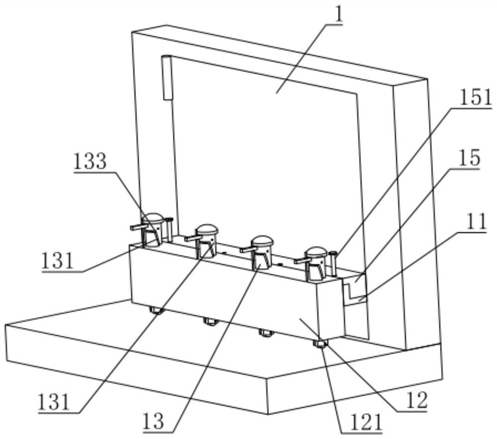
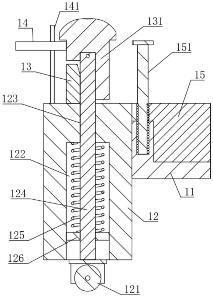
[0023] Embodiment 1: a kind of reinforced concrete protective equipment, such as figure 1 and figure 2 , including a door frame installed in the wall to match the wall hole and a door leaf 1 rotatably connected to one side of the door frame. At this time, there is a gap between the door leaf 1 and the ground, and the side of the door leaf 1 is provided with an L-shaped clamping plate 11. The clamping plate 11 is arranged on the side of the door leaf 1 away from the door frame, and the door leaf 1 is clamped with a fixed block 12 by the L-shaped clamping plate 11, and the lower end surface of the fixed block 12 is provided with some universal wheels 121 that conflict with the ground.
[0024] like figure 1 and figure 2 , when the fixed block 12 is clamped on the door leaf 1 through the clamping plate 11, the universal wheel 121 at the lower end of the fixed block 12 is in conflict with the ground at this time, which is equivalent to the universal wheel 121 installed on the ...
Embodiment 2
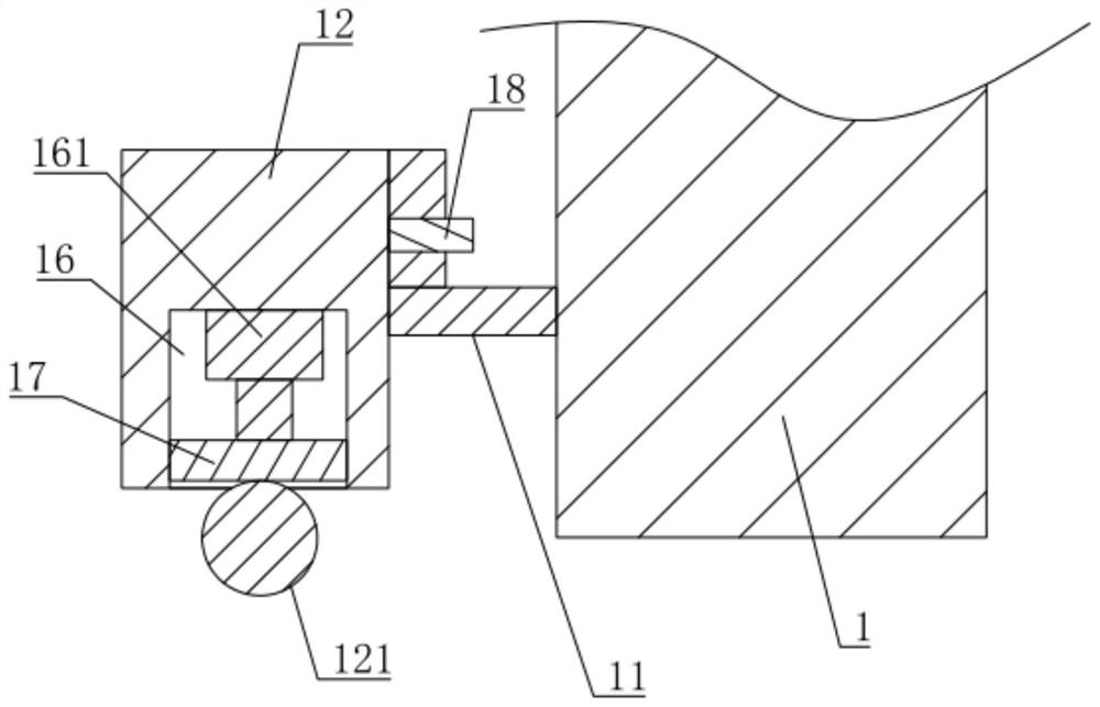
[0032] Embodiment 2: a kind of reinforced concrete protective equipment, such as image 3 , the difference from Embodiment 1 is that the telescopic element includes a placement groove 16 on the side of the fixed block 12 facing the ground, the bottom of the placement groove 16 is provided with a cylinder 161, and the universal wheel 121 is fixed on the piston rod of the cylinder 161 superior. At this time, the cylinder 161 drives the universal wheel 121 to move downward, so that the universal wheel 121 provides support for the door leaf 1 and at the same time facilitates the user to push the door leaf 1 .
[0033] like image 3 , the connecting plate 17 is slidingly connected in the placement groove 16, each universal wheel 121 is fixed on the connecting plate 17, the number of the cylinder 161 is one and the piston rod of the cylinder 161 and the connecting plate 17 are away from the side of the universal wheel 121 connect. The setting of the connecting plate 17 is conveni...
PUM
 Abstract
Description
Claims
Application Information
 - R&D Engineer
- R&D Manager
- IP Professional
- Industry Leading Data Capabilities
- Powerful AI technology
- Patent DNA Extraction
Browse by: Latest US Patents, China's latest patents, Technical Efficacy Thesaurus, Application Domain, Technology Topic, Popular Technical Reports.
© 2024 PatSnap. All rights reserved.Legal|Privacy policy|Modern Slavery Act Transparency Statement|Sitemap|About US| Contact US: help@patsnap.com


