Aluminum alloy door and window with drainage mechanism
An aluminum alloy door and window, water-repellent technology, applied in the field of doors and windows, can solve the problems of inconvenient drainage of rainwater and downward flow of rainwater.
- Summary
- Abstract
- Description
- Claims
- Application Information
AI Technical Summary
Problems solved by technology
Method used
Image
Examples
Embodiment 1
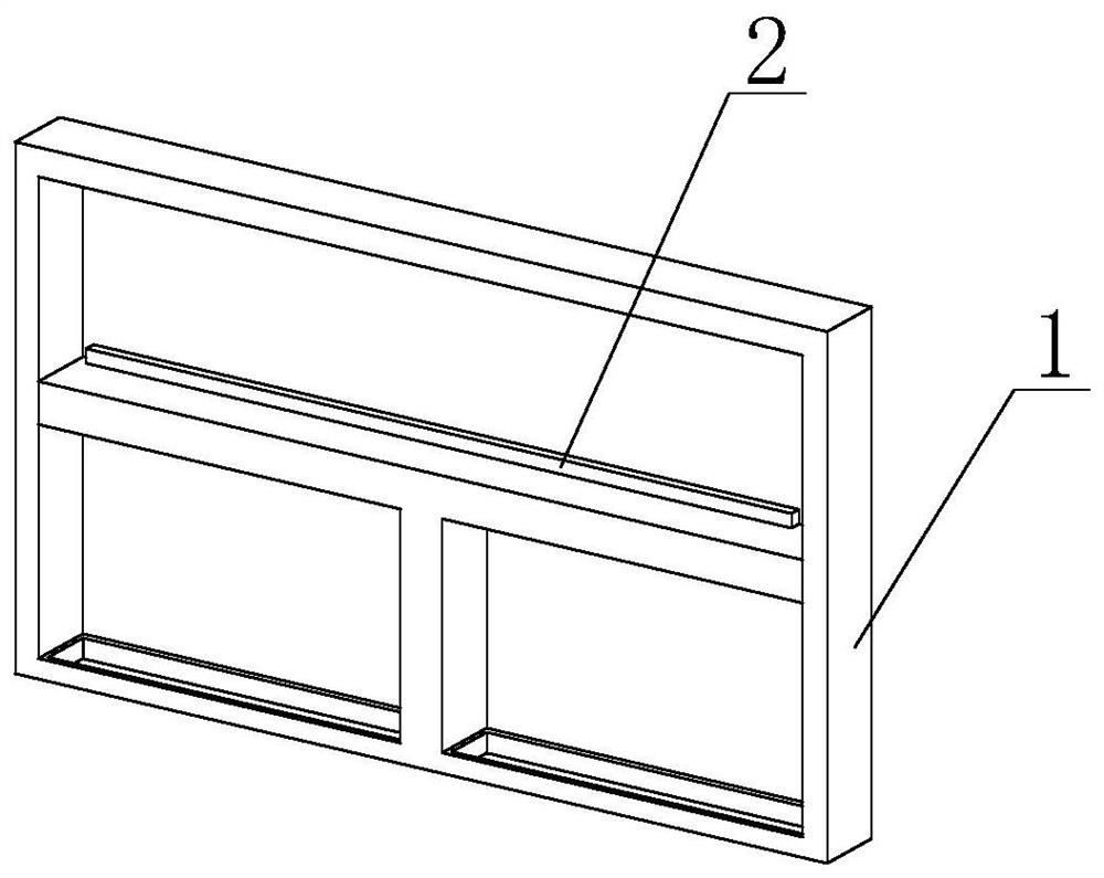
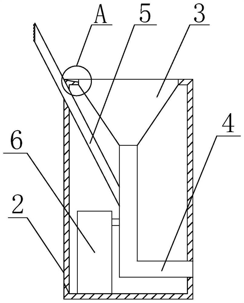
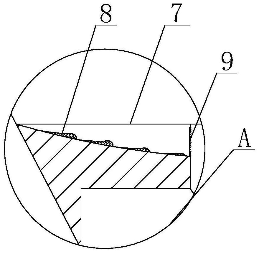
[0029] Such as Figure 1-Figure 7 As shown, the present invention provides an aluminum alloy door and window with a hydrophobic mechanism, comprising a window 1 and a water storage device 2, the bottom of the water storage device 2 is fixedly connected to the outer wall of the window 1, and the water storage device 2 includes a water flow collecting bucket 3. The discharge pipe 4, the baffle plate 5 and the air flow change chamber 6, the bottom of the water flow collection bucket 3 is connected to the top of the discharge pipe 4, the bottom of the baffle plate 5 is connected to the outer wall of the discharge pipe 4, and the bottom of the air flow change chamber 6 It is fixedly connected with the bottom of the inner wall of the water storage device 2, the inner wall of the discharge pipe 4 is provided with a sealing block 13, the outer wall of the sealing block 13 is slidingly connected with the inner wall of the discharge pipe 4, and the inner wall of the baffle plate 5 is fix...
Embodiment 2
[0033] Such as Figure 5 As shown, on the basis of Embodiment 1, the present invention provides a technical solution: the air flow change chamber 6 includes a connection plate 14, a pressurization chamber 15, a connection column 16, a shaft sleeve 17 and a gas conduit 22, and the outer wall of the connection plate 14 It is slidingly connected with the inner wall of the airflow changing chamber 6, the left side of the connecting plate 14 is fixedly connected with the right side of the shaft sleeve 17, the inner wall of the shaft sleeve 17 is slidingly connected with the outer wall of the connecting column 16, and the top of the connecting column 16 is connected with the airflow changing chamber 6 The top of the inner wall is fixedly connected, the bottom of the connecting column 16 is fixedly connected with the top of the pressurized chamber 15, the top of the gas conduit 22 is connected through the bottom of the pressurized chamber 15, and when the connecting plate 14 moves dow...
Embodiment 3
[0035] Such as Figure 6-7 As shown, on the basis of Embodiment 1 and Embodiment 2, the present invention provides a technical solution: preferably, the inner wall of the window 1 is provided with a placement pipe 23 and a hydrophobic device 24, and the top of the placement pipe 23 and the water storage device The bottom of 2 is through-connected, and one side of the hydrophobic device 24 is connected through the outer wall of the placement tube 23, and the placement tube 23 is arranged on both sides of the hydrophobic device 24, and the bottom of the hydrophobic device 24 is fixedly connected with the bottom of the inner wall of the window 1, and the draining Device 24 comprises support column 25, hydrophobic plate 26, trapezoidal block one 27, elastic support 28, trapezoidal block two 29 and ball 30, the both sides of support column 25 are fixedly connected with the inwall of hydrophobic device 24, the inwall of trapezoidal block one 27 Slidably connected with the outer wall...
PUM
 Abstract
Description
Claims
Application Information
 - R&D
- Intellectual Property
- Life Sciences
- Materials
- Tech Scout
- Unparalleled Data Quality
- Higher Quality Content
- 60% Fewer Hallucinations
Browse by: Latest US Patents, China's latest patents, Technical Efficacy Thesaurus, Application Domain, Technology Topic, Popular Technical Reports.
© 2025 PatSnap. All rights reserved.Legal|Privacy policy|Modern Slavery Act Transparency Statement|Sitemap|About US| Contact US: help@patsnap.com


