Photoelectric detection system based on power coding, control method and coding method

A photoelectric detection and coding technology, applied in the direction of optical device exploration, etc., can solve the problems of strong anti-interference ability of detection equipment, increased design cost of software and hardware, complicated wiring of detection equipment, etc., to facilitate transmission and reception synchronization, improve wiring Flexibility, the effect of improving system efficiency and stability

Pending Publication Date: 2021-06-11
WUXI DECHIP MICROELECTRONICS CO LTD
View PDF0 Cites 1 Cited by
  • Summary
  • Abstract
  • Description
  • Claims
  • Application Information

AI Technical Summary

Problems solved by technology

[0004] With the popularization of automation applications, the number of photoelectric transmitting and receiving pairs in the photoelectric detection system has increased, and the requirement for the cascading distance of photoelectric transmitting and receiving has increased, resulting in more complicated wiring in the detection equipment and increased installation difficulty.
In addition, due to the different application fields, the anti-interference ability of the detection equipment is highly required, which leads to an increase in the cost of anti-interference software and hardware design

Method used


Image

  • Photoelectric detection system based on power coding, control method and coding method
  • Photoelectric detection system based on power coding, control method and coding method
  • Photoelectric detection system based on power coding, control method and coding method

Examples


Embodiment Construction

[0038] The present invention will be further described below in conjunction with specific drawings and embodiments.

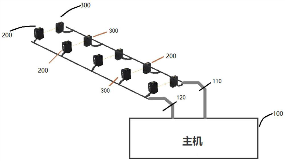
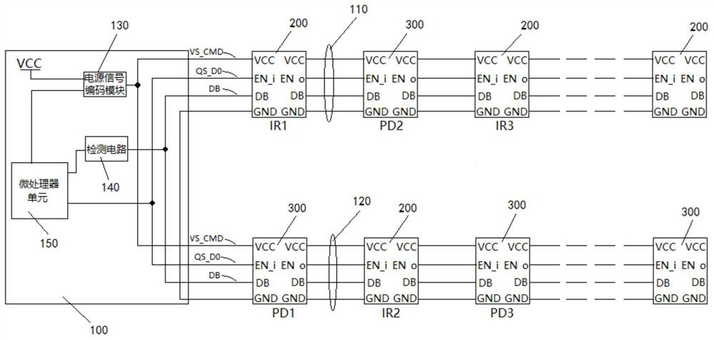
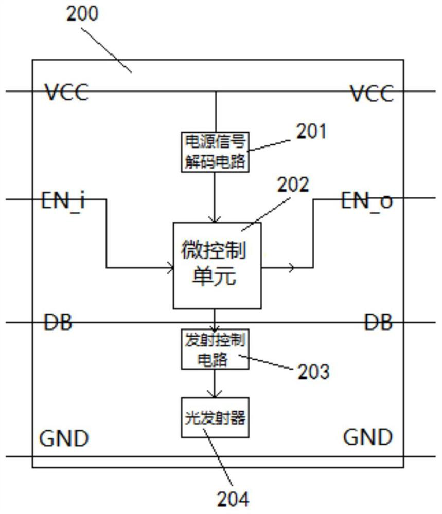
[0039] Such as figure 1 As shown: in order to simplify the detection system, improve the anti-interference ability and reduce the accumulation of timing errors caused by cascading multiple points in the system, and at the same time realize flexible installation and reduce costs, the present invention includes a host 100 and at least two photoelectric transmitting and receiving pairs, The photoelectric transmitting and receiving pair includes a photoelectric transmitting unit 200 and a photoelectric receiving unit 300 adapted to the photoelectric transmitting unit 200; the host 100 is adapted to connect with the photoelectric transmitting and receiving pair through two photoelectric detection connection lines, wherein , for any photoelectric transmitting and receiving pair, the photoelectric transmitting unit 200 in the photoelectric transmitting and receiving p...


PUM


Abstract

The invention relates to a photoelectric detection system based on power coding, a control method and a coding method. The system comprises a host and at least two groups of photoelectric emission and reception pairs, for any photoelectric emission and reception pair, a photoelectric emission unit in the photoelectric emission and reception pair is adaptively connected with one photoelectric detection connection line group, and a photoelectric reception unit in the photoelectric emission and reception pair is adaptively connected with the other photoelectric detection connection line group; for any photoelectric detection connecting line group, the power supply signal bus in the photoelectric detection connecting line group can be used for supplying power to the photoelectric emission unit or the photoelectric emission unit and the photoelectric receiving unit which are connected to the photoelectric detection connecting line group; the photoelectric emission unit or the photoelectric emission unit and the photoelectric receiving unit which are connected to the photoelectric detection connecting line group are connected in series step by step according to a required sequence; according to the invention, the detection system can be simplified, the anti-interference capability can be improved, the time sequence error accumulation caused by multi-point cascading of the system can be reduced, flexible installation can be achieved, and the cost can be reduced.

Description

technical field [0001] The invention relates to a photoelectric detection system, a control method and a coding method, in particular to a photoelectric detection system, a control method and a coding method based on power coding. Background technique [0002] In civil and industrial automation fields such as turnstiles, elevators, stamping equipment, and automated production lines, detection equipment usually uses through-beam photoelectric sensors to detect and judge the passage of people and objects. In these detection devices, the photoelectric transmitting and receiving pair as the detection unit is usually composed of a certain number of photoelectric sensors. With the popularization of automation applications, the number of photoelectric transmitting and receiving pairs is required to increase, the distance of photoelectric transmitting and receiving pairs to be cascaded is getting farther and farther, and the installation method is required to be more and more flexib...

Claims


Application Information

Patent Timeline
Patent Type & Authority Applications(China)
IPC IPC(8): G01V8/20
CPCG01V8/20
Inventor 周龙江
Owner WUXI DECHIP MICROELECTRONICS CO LTD
Why Eureka
Try Eureka