
A compact vibration-absorbing and heat-dissipating device for a motherboard

A heat dissipation device, a compact technology, applied in instruments, computing, electrical and digital data processing, etc., can solve the problems of small vibration reduction and heat dissipation structure, small space occupation, large space occupation, etc., to solve vibration reduction and heat dissipation, reduce Vibration, small footprint effect

Active Publication Date: 2022-08-05
深圳市智微智能软件开发有限公司
View PDF7 Cites 0 Cited by
  • Summary
  • Abstract
  • Description
  • Claims
  • Application Information

AI Technical Summary

Problems solved by technology

Some existing motherboards are also equipped with vibration reduction and heat dissipation devices, but these vibration reduction and heat dissipation devices generally have the problems of bulky structure and large space occupation; for field vehicles, on the premise of satisfying vibration reduction and heat dissipation, the vibration reduction and heat dissipation structure is also pursued. As small as possible, occupying as little space as possible, which is very important for sophisticated circuit control systems

Method used


Image

  • A compact vibration-absorbing and heat-dissipating device for a motherboard
  • A compact vibration-absorbing and heat-dissipating device for a motherboard
  • A compact vibration-absorbing and heat-dissipating device for a motherboard

Examples


Embodiment 1

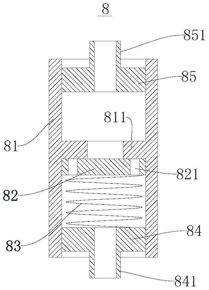
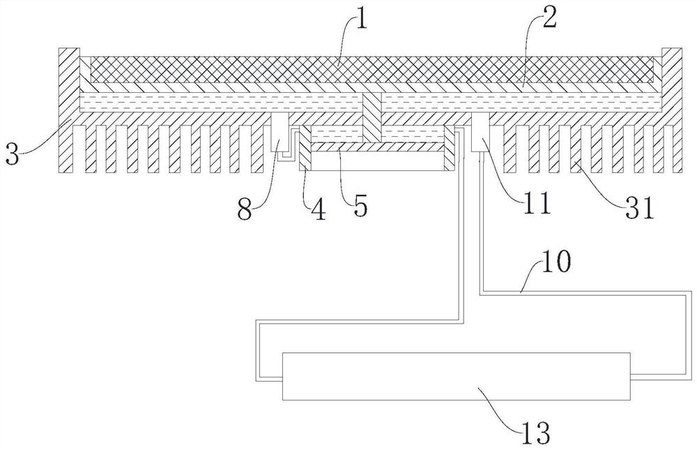
[0023] Example 1: as figure 1 As shown, a compact vibration reduction and heat dissipation device for a mainboard includes an outer base 3 with an upper end opening, an inner base 2 is arranged in the upper end opening of the outer base 3, and the main board 1 is fixed on the inner base 2. A first space A for accommodating the cooling liquid 12 is formed between the bottom of the outer seat body 3 and the bottom of the inner seat body 2, and the outer end surface of the inner seat body 2 is sealed with the inner surface of the outer seat body 3, so that the cooling liquid 12 cannot Leakage from the joint surface can be solved by high-precision coordination at the joint surface. Since the pressure of the coolant 12 is relatively small and the viscosity of the coolant 12 is relatively high, the high-precision coordination can ensure that there is no leakage here; in order to reduce the processing time To ensure the accuracy or to further ensure the sealing effect, a sealing rubb...

Embodiment 2

[0027] Embodiment 2: as image 3 , and other structures are the same as those of the first embodiment, except that a cooling chamber 13 is added on the basis of the first embodiment, and the cooling chamber 13 is connected to the first conduit 10 in series. The cooling chamber 13 is generally arranged at a position away from the high temperature parts, and the cooling liquid 12 can obtain better heat dissipation effect when flowing through the cooling chamber 13 . At the same time, the cooling chamber 13 is preferably a deformable flexible soft bag, so that the cooling chamber 13 can be packed and fixed in an irregular space, and there is no need to separately plan the space for placing the cooling chamber 13, so as to make the structure more compact.


PUM


Abstract

The present invention involves a compact vibration reduction and heat dissipation device of a motherboard, including the outer body and the upper end of the outer body.The sealing cooperation, the first space of the bottom of the outer body and the bottom of the inner seat; the outer body of the outer body is set with a cylinder body, and there is a piston in the cylinder.The connecting rod passes through the bottom of the outer body and is fixed with the inner body. The connecting rod can be coordinated with the bottom of the outer body. The piston and the bottom of the outer body form a second space.The first space and the second space are turned on into one -way circulation pathway. One of the one -way valve is responsible for flowing the cooling solution of the first space into the second space. The other one -way valve is responsible forThe cooling fluid of the space flows into the first space.The invention has the advantages of compact structure and small space.

Description

technical field [0001] The invention relates to the technical field of heat dissipation and vibration reduction of mainboards, and more particularly, to a compact vibration reduction and heat dissipation device for mainboards. Background technique [0002] The motherboard is generally a rectangular circuit board, on which many important circuit systems are installed, such as BIOS chips, I / O control chips, expansion slots and other components. For field vehicles, they are often equipped with very complex electronic systems; due to the harsh field conditions, the vibration of the vehicles is large, and the electronic systems often carry a large workload, resulting in relatively high vibration and temperature of the main board. In order to ensure the stability of the main board To work reliably, it is necessary to set up a vibration-absorbing and heat-dissipating structure. Some existing motherboards are also equipped with vibration reduction and heat dissipation devices, but ...

Claims


Application Information

Patent Timeline
Patent Type & Authority Patents(China)
IPC IPC(8): G06F1/20
CPCG06F1/20
Inventor 谭信平李博王谦
Owner 深圳市智微智能软件开发有限公司
Learn More