
Electric leakage protection device

A technology of leakage protection device and current detection device, applied in emergency protection circuit devices, circuit devices, emergency protection devices with automatic disconnection, etc., can solve the problems of inability to meet the power supply system, voltage divider reduction, negative voltage drift, etc.

Pending Publication Date: 2021-06-11
CHONGQING CRRC RAILWAY VEHICLES CO LTD
View PDF4 Cites 3 Cited by
  • Summary
  • Abstract
  • Description
  • Claims
  • Application Information

AI Technical Summary

Problems solved by technology

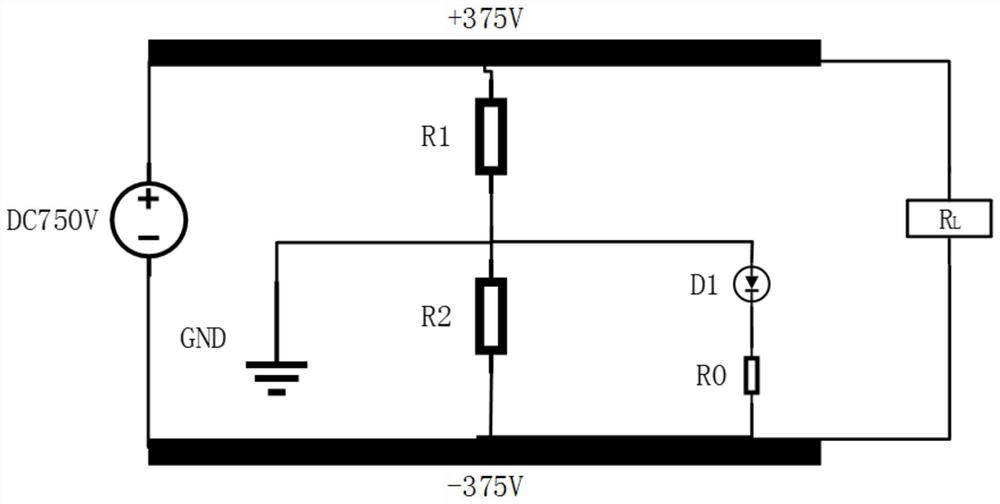
When the power supply system is ±DC375V or ±DC750V, such as figure 1 As shown, since the voltage applied to the leakage protection resistor R0 is 375V, a large current will flow through the leakage protection resistor R0 and the silicon stack D1, causing the trip signal to be triggered. The parallel connection of the protection resistor R0 and the second resistor R2 causes the voltage division across the second resistor R2 to decrease, and the negative electrode voltage drifts, which cannot meet the requirements of the power supply system

Method used


Image

  • Electric leakage protection device
  • Electric leakage protection device
  • Electric leakage protection device

Examples


Embodiment Construction

[0025] The following will clearly and completely describe the technical solutions in the embodiments of the present application with reference to the drawings in the embodiments of the present application. Obviously, the described embodiments are only some of the embodiments of the present application, not all of them. Based on the embodiments in this application, all other embodiments obtained by persons of ordinary skill in the art without making creative efforts belong to the protection scope of this application.

[0026] The core of the present application is to provide a leakage protection device capable of judging the leakage of the positive or negative pole of the busbar without affecting the requirements of the power supply system.

[0027] In order to enable those skilled in the art to better understand the solution of the present application, the present application will be further described in detail below in conjunction with the drawings and specific implementation ...


PUM


Abstract

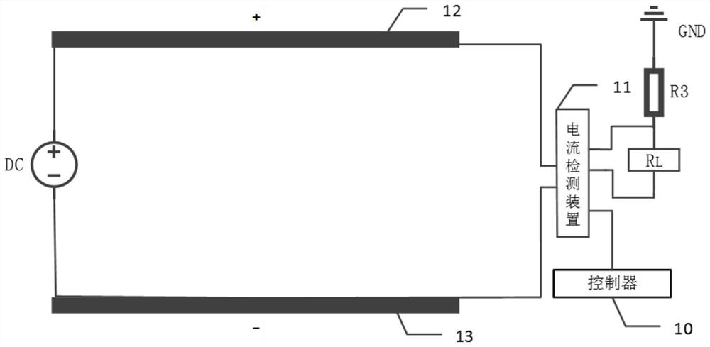
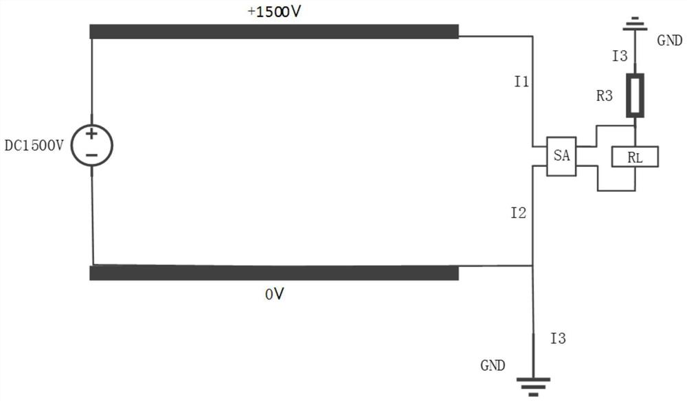
The invention discloses an electric leakage protection device which comprises a controller and a current detection device connected with a bus positive electrode and a bus negative electrode, the current detection device can detect current flowing through the bus positive electrode and the bus negative electrode, and then the controller judges whether electric leakage exists on the load side of the electric leakage protection device or not according to current changes. Corresponding processing is carried out during electric leakage, so that protection of the power supply equipment is realized. Meanwhile, the detection device only detects the current and is not connected to an original closed loop, so that the voltage of the bus positive electrode and the bus negative electrode does not drift, and the electric leakage condition of the bus positive electrode or the bus negative electrode can be judged under the condition that the requirement of a power supply system is not influenced.

Description

technical field [0001] The present application relates to the technical field of leakage protection, in particular to a leakage protection device. Background technique [0002] Leakage protection devices are used to protect power supply equipment and personnel. The power supply system of the existing monorail DC power supply system is generally to add a leakage protection resistor R0 and a unidirectional conductive silicon stack D1 between the negative pole and the ground as a leakage protection device for leakage protection. When the power supply system is 0, DC1500V, when the positive pole leaks to the ground, the current returns from the ground to the negative pole through the leakage protection resistor R0 and the silicon stack D1, thereby triggering an alarm or trip signal to protect the power supply system. When the power supply system is ±DC375V or ±DC750V, such as figure 1 As shown, since the voltage applied to the leakage protection resistor R0 is 375V, a large cu...

Claims


Application Information

Patent Timeline
Patent Type & Authority Applications(China)
IPC IPC(8): H02H3/28H02H3/04
CPCH02H3/28H02H3/04
Inventor 陈卫兵姚鸿洲姚平黄伟梁廖泳竣胡涵赵益林陈海波何昌艳
Owner CHONGQING CRRC RAILWAY VEHICLES CO LTD
Learn More