Automatic corner cutting operation method and device

A working device and corner cutting technology, which is applied in metal processing, sorting, etc., can solve the problems of large impact, difficult memory stick identification, labor-intensive, etc., and achieve the effects of reduced defective rate, high processing efficiency, and labor saving

Active Publication Date: 2020-06-23
信泰电子(西安)有限公司
View PDF11 Cites 0 Cited by
  • Summary
  • Abstract
  • Description
  • Claims
  • Application Information

AI Technical Summary

Problems solved by technology

[0004] The above-mentioned existing technical solutions have the following defects: after classifying the memory sticks, workers usually mark the type of the memory sticks by marking the memory sticks with an array mark, and then manually sort the memory sticks according to the array mark, but This is greatly affected by the status of the workers, and it is labor-intensive. If automatic equipment is used for sorting, the marking position will be different due to the different types of memory sticks. It is difficult for the automatic sorting equipment to distinguish the type of memory sticks, resulting in automatic sorting. The sorting result is inaccurate

Method used


Image

  • Automatic corner cutting operation method and device
  • Automatic corner cutting operation method and device

Examples


Embodiment 1

[0050] Embodiment one: a kind of corner cutting automatic operation method, concrete steps are as follows:

[0051]Step 1. Open two adjacent holes on one side of each workpiece, and the distance between the two holes is different for different types of workpieces. The control system registers the positions of the two holes on the workpiece as coded holes that distinguish each workpiece. Open another two adjacent holes on the other side of the workpiece away from the coding hole, and record the distance between the two holes for numbering. When the device drills holes on workpieces, the distance between the two holes on the next workpiece increases by a set distance every time a workpiece passes through in sequence.

[0052] Step 2, storing the distance between two holes on each kind of workpiece.

[0053] Step 3, processing the first workpiece of each kind of workpiece and performing quality inspection.

[0054] Step 4: If the test is qualified, proceed to the next step, an...

Embodiment 2

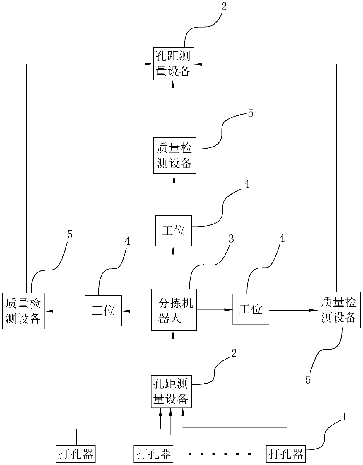
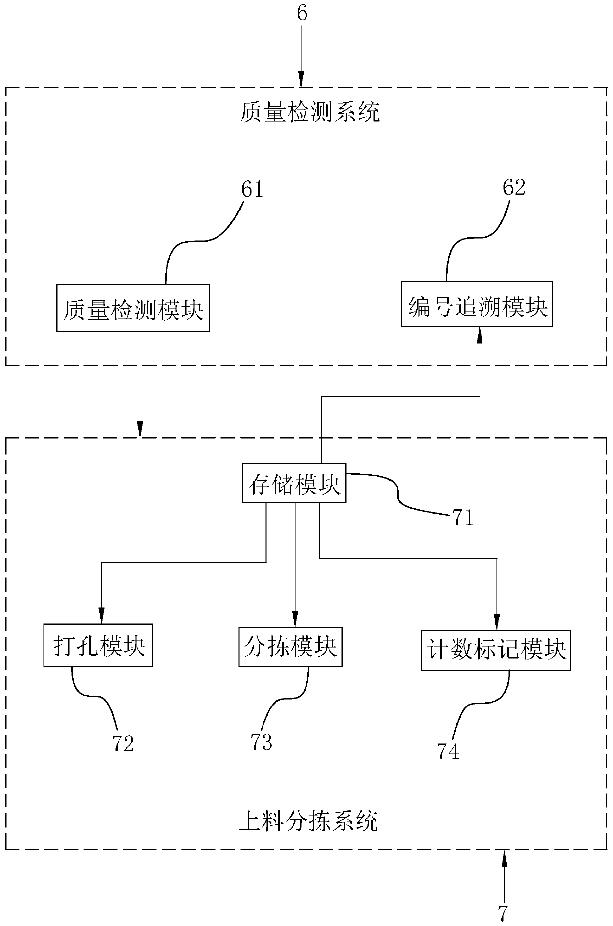
[0062] Embodiment 2, a kind of chamfering automatic operation system, such as figure 1 and figure 2 As shown, it includes several stations 4, puncher 1, sorting robot 3, hole distance measurement equipment 2 and quality inspection equipment 5, hole puncher 1, sorting robot 3, hole distance measurement equipment 2 and quality inspection equipment 5 Connect the control system. The control system includes a feeding sorting system 7 and a quality inspection system.

[0063] Such as figure 1 and figure 2 As shown, the loading and sorting system 7 includes a counting and marking module 74 , a punching module 72 , a storage module 71 and a sorting module 73 . The quality detection module 616 includes a quality detection module 616 and a serial number tracing module 62 . The storage module 71 stores punching distance information and set distances of different types of workpieces, the storage module 71 sends the punching distance information to the corresponding punching module ...


PUM


Abstract

The invention discloses an automatic corner cutting operation method and device, and belongs to the technical field of memory bank processing. The automatic corner cutting operation device comprises aplurality of stations, a puncher, a sorting robot, hole distance measuring equipment and quality detecting equipment, and the puncher, the sorting robot, the hole distance measuring equipment and thequality detecting equipment are connected with a control system; the control system comprises a feeding sorting system and a quality detection system; the feeding sorting system comprises a punchingmodule, a storage module and a sorting module; and the punching module is connected with the puncher, the sorting module is connected with the sorting robot and the hole distance measuring equipment,and the quality detection system is connected with the quality detecting equipment. The automatic corner cutting operation device has the advantages that sorting is more reliable and stable, accidentsare not prone to happening, the processing efficiency is effectively improved, and the defective rate is reduced.

Description

technical field [0001] The invention relates to the technical field of memory stick processing, in particular to an automatic corner cutting method and device. Background technique [0002] At present, in the process of memory stick processing, it is necessary to cut the corners of the memory sticks, that is, cut a curved surface at the slot of the memory sticks, so that the memory sticks can be inserted into the motherboard and other places more easily. Different memory sticks need to cut corners. The radian and other data are different, and the memory modules need to be classified before corner cutting. [0003] For the prior art, reference may be made to the Chinese invention patent application publication number CN108205105A, which discloses an automatic insertion and removal mechanism for memory sticks of test equipment. It includes a case with a 45° slope and a feature recognition device perpendicular to the top of the case slope. An upper guide rail and a lower guide...

Claims


Application Information

Patent Timeline
Patent Type & Authority Applications(China)
IPC IPC(8): B26D7/27B07C5/00B07C5/04B07C5/36
CPCB07C5/00B07C5/04B07C5/361B07C2501/0063B26D7/27
Inventor 蔡景灵胡亚涛王攀峰周俊杰
Owner 信泰电子(西安)有限公司
Why Eureka
Try Eureka