[0033] Next, the technical solutions in the embodiments of the present invention will be apparent from the embodiment of the present invention, and it is clearly described, and it is understood that the described embodiments are merely embodiments of the present invention, not all of the embodiments. Based on the embodiments of the present invention, there are all other embodiments obtained without making creative labor without making creative labor premises.
[0034] In the description of the present invention, it is to be understood that the terms "upper", "lower", "front", "post", "left", "right", "top", "bottom", "inside", " The orientation or positional relationship of the instructions such as "is based on the orientation or positional relationship shown in the drawings, which is merely description of the present invention and simplified description, rather than indicating or implying that the device or component must have a specific direction. Specific orientation constructs and operations are therefore not to be construed as limiting the invention.
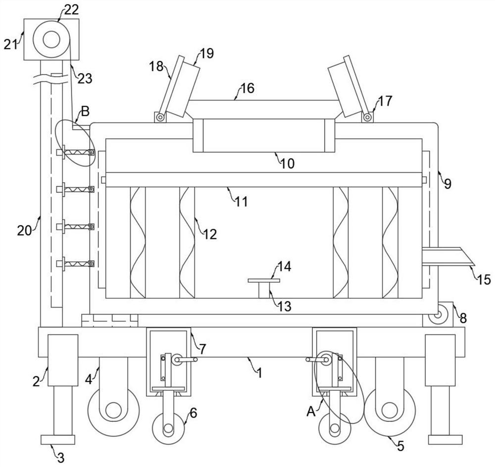
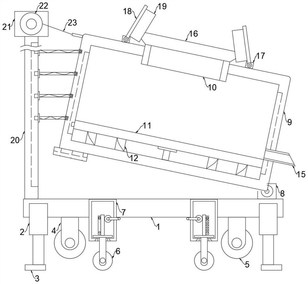
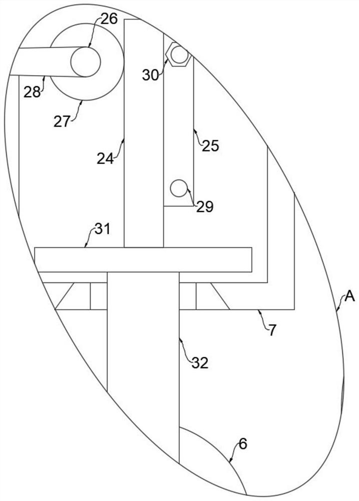
[0035] Refer Figure 1-5 One railway rail transport vehicle is connected to the transition adjustment device, including the bottom plate 1, and two hydraulic rods 2 are fixedly mounted on the bottom plate 1, and the driving ends of the two hydraulic rods 2 are fixedly mounted, and the bottom plate 1 is fixedly mounted There are a plurality of connecting frames 4, and each of the connecting frames 4 is rotated and mounted having a wheel 5, and a plurality of fixed rods 7 are fixed to the bottom plate 1, and the moving plate 31 is slidably mounted on each fixing rod 7, and each The lower portion of the moving plate 31 is rotated by the support frame 32, and the upper portion of each of the moving plates 31 is fixedly mounted, and each fixing rod 7 is rotated through the turn rod 26, and the gear 27 is rotated. And each gear 27 is fitted with the right position of the right position, and the engaging mechanism is mounted between each of the shoulders 24 and the corresponding fixed rod 7;
[0036] The above is worth paying attention to:
[0037] 1. The wheel 5 is rotated at the bottom of the bottom plate 1, and when the device is required to travel on the ground road, it is only necessary to make the wheel 5 to the ground.
[0038]2, when the device is required to travel on the railway track, simply start the two hydraulic rod 2 to lower the drive end to the lower portion of the wheel 5, and take the entire unit, turn the rod 26 to drive the gear 27 Thus, the ripple 24 is moved down, and the rod 24 is moved down to drive the moving plate 31, and the support frame 32 is moved down, and the rail wheel 6 is engaged with the railway track, and then recover the hydraulic rod 2 to the initial state. At this time, the track wheel 6 can be used to travel on the railway track.
[0039] 3, the engaging mechanism includes the engaging plate 25 fixed to the nip 24, and the fixing rod 7 is applied with the positioning pin 30, and two engagement holes 29 are mating with the positioning pin 30 on the engaging plate 25, When the position adjustment of the track wheel 6 is completed, the positioning pin 30 can be engaged into the engaging hole 29 of the corresponding position on the engaging plate 25, that is, the engagement plate 25, the nip 24, the support frame 32 and the track wheel 6 The height position is fixed.
[0040] 4, each passing rod 26 is fixedly mounted, and the transfer 28 is fixed, and the rotatable rotor 28 is rotated to rotate the rotary rod 27 and the gear 27, which is more convenient to save.
[0041] 5, the bottom of each of the pads 3 is fixedly mounted, and the rubber pad can be used to protect the pad 3 and the friction between the pad 3 and the ground can be more secure.
[0042] The upper portion of the bottom plate 1 is attached to the base 8, the vertical rod 20, and the base 8 is mounted with a transition box 9 through the positioning axis, and the bottom portion of the transition box 9 is fixedly mounted, and the transition box 9 is installed through the sliding mechanism. The collecting plate 11, and a plurality of compression spring 12 is fixed to the bottom wall of the collecting plate 11 and the transition box 9, and the finite plate 14 is fixed to the transition box 9, and the restricted plate 14 is fixed. The alarm is mounted, and the feed tube 10 is attached to the transition box 9, and the tube 10 is attached to the feed tube 10, and two damping shafts 17 are fixed to the transition box 9, and two The damping shaft 17 is located on both sides of the feed tube 10, and the two damping shafts 17 are rotated by the connecting rod 18, and there is an adsorption mechanism between each connecting rod 18 and the transition box 9;
[0043] The above is worth paying attention to:
[0044] 1. When the coal enters the transition box 9 from the feed tube 10, the connecting rod 18 can be rotatably located on the side of the feed tube 10, and then open the dust cover 19 on the connecting rod 18, at this time The cover 19 can protect the periphery of the feed tube 10 so that the coal dust will not be randomly drifted when the feed is carried out.
[0045] 2, the adsorbent mechanism includes a magnet 1 mounted on the connecting rod 18, and the magnet 2 is fixed to the transition box 9, and the magnet is opposite to one side of the magnets close to each other, and when the dust cover 19 is not required Simply rotate the connecting rod 18 so that the magnets on which the magnets thereon is suck the magnet diacene, the connecting rod 18, the dust cover 19 is fixed to the upper portion of the transition box 9.
[0046] 3, the sliding mechanism includes a trapezoidal slider fixed to the collecting plate 11, and a ladder slide is opened in the transition box 9, and the trapezoidal slider is engaged in the trapezoidal slot, the sliding mechanism is used to enable the collecting plate 11. The up and down movement can only be performed in the transition box 9 without the offset and separation between the transition box 9.
[0047] 4. The opening and closing mechanism includes two fixed blocks that are fixed to the feed tube 10, and both fixed blocks are rotated by the reset roller, and the two opening and closing doors are engaged with each other, two fixation The finite bit rod is fixed on the block, and the two limit rods are located at the upper part of the two set, and the flare mechanism is used to control the opening and closing state of the feed tube 10. When the coal enters the transition box 9, this At the time of the opening and closing door, the opening and closing door will be pressed, and when the coal is not performed, the opening and closing door is automatically closed under the action of the reset roller, so that coal in the transition box 9 and coal. The gray dust does not enter the outside air through the feed tube 10.
[0048] 5, the initial position of the collecting plate 11 is located on the upper portion of the transition box 9, and the coal will be pressed down from the feed tube 10 to the transition box 9, and the collecting plate 11 is lowered, and the coal will be accumulated on the collecting plate 11. Thus, the grocery of the coal into the transition box 9 is always constant, thereby causing the coal to produce more coal ash due to the high degree of decrease.
[0049] 6, the upper portion of the feed tube 10 is fixedly mounted having a cover 16, and the cover body 16 can increase the feed range of the feed tube 10, and can prevent the action of the coal ash scatter.
[0050] The vertical rod 20 is rotated by the traction motor 21 by the traction motor 21, and the traction plate 36 is fixed to the transition box 9, and the traction plate 36 and the winding roller 22 are fixedly connected to the traction rope 23, the transition box 9 and stand A plurality of mobile mechanisms are installed between the rods 20;
[0051] The above is worth paying attention to:
[0052] 1. When the discharge of the coal is required, only the traction motor 21 is started to rotate the winding roller 22, and the winding roller 22 is rotated, and the traction rope 23 will be retracted to pull the transition box 9 to move, transition box 9 When moving, the base 8 is moved under the position of the base 8. At this time, the coal in the transition box 9 will be quickly removed from the discharge tube 15 under the action of gravity.
[0053] 2, the moving mechanism includes fixed block 34 fixed to the transition box 9, and the restricted spring rod 35 is rotated on the limit block 34, and the rotary rod 20 is mounted by the limit structure, and the retractable spring rod 35 Attaching one end of the restricted block 34 is fixed to the moving block 33, the moving mechanism is used to make the transition box 9 does not have a large vibration in the inclinement, thereby making the tilt process more smooth.
[0054] 3, the limit structure includes a trapezoidal jacket that is fixed to the moving block 33, and the vertical rod 20 is opened on the vertical rod 20, and the limit structure functions as a limit. The moving block 33 can only be pulled on the vertical rod 20 without the offset and separation between the vertical rod 20.
[0055] Further, the above fixed connection is further understood, unless otherwise specified and defined, it is possible to be welded, and may be welded, or a conjunctionery, or integrally formed setting, etc., which is well known to those skilled in the art.
[0056] It should be noted that in this article, a relationship term such as the first and second, etc. is only used to separate an entity or operation with another entity or an operational area, without having to require or imply these entities or operations. There is any such practical relationship or order. Moreover, the term "comprising", "comprising" or any other variable is intended to encompass non-exclusive contained, so that the process, method, article, or device including a series of elements, not only those elements, but also not expressly listed. Other elements, or elements that are also inherent to this process, method, item, or device.
[0057] As described above, only the preferred embodiments of the present invention are preferred, but the scope of the invention is not limited thereto, and any techniques, those skilled in the art, according to the present invention, in accordance with the present invention. And its inventive concept is equivalent to alternative or change, which should be covered within the scope of the invention.