
Novel multi-component spinning spinneret plate

A spinneret and multi-component technology, applied in the field of spinning, can solve the problems of single structure and inability to manufacture fibers, and achieve the effects of prolonging service life, uniform filament output, and promoting melt flow.

Pending Publication Date: 2021-06-15
SUZHOU LONGJIE SPECIAL FIBER
View PDF0 Cites 0 Cited by
  • Summary
  • Abstract
  • Description
  • Claims
  • Application Information

AI Technical Summary

Problems solved by technology

The function of the spinneret is to transform the viscous polymer melt or solution into a fine flow with a specific cross-section through the micropores, and to form filaments after being solidified by a coagulation medium such as air or a coagulation bath. The spinneret can There are three kinds of spinnerets: common type, special-shaped spinneret and composite spinneret. The most critical structural features of the spinneret include the plate structure and the spinneret hole structure. The hole shape of the spinneret hole should be changed according to different spinning requirements. Now The holes with spinnerets are mainly circular holes with a single structure and cannot produce fibers with unique structures

Method used

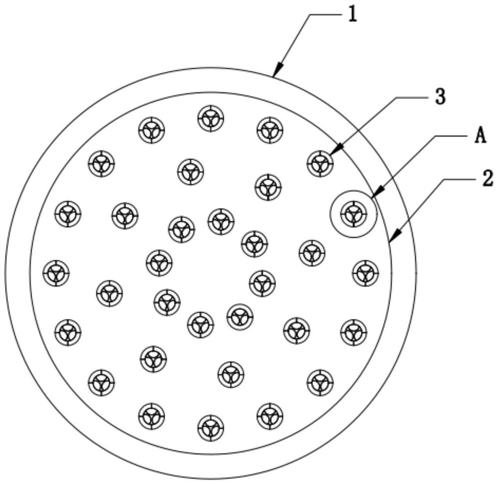
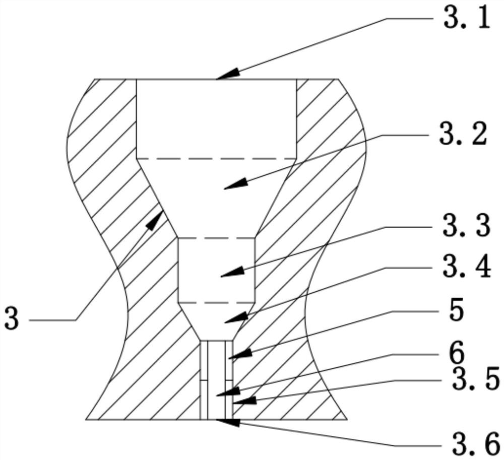
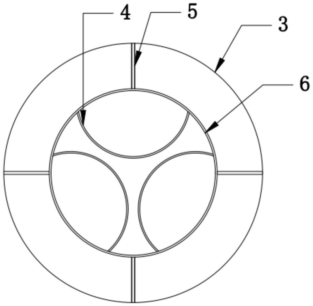

Image

  • Novel multi-component spinning spinneret plate
  • Novel multi-component spinning spinneret plate
  • Novel multi-component spinning spinneret plate

Examples


Embodiment 1

[0017] combined with Figures 1 to 3 , a new type of spinneret for multi-component spinning, including a spinneret body, the spinneret body includes a feed plate 1 and a discharge plate 2, and the discharge plate 2 is provided with several The spinneret hole 3, the spinneret hole 3 is provided with a connecting plate 5, one end of the connecting plate 5 is connected with an annular baffle 6, and the annular baffle 6 is provided with an arc The baffle 4, the end of the spinneret hole 3 close to the feed plate 1 is the feed port 3.1, and the spinneret hole 3 is provided with a first deceleration chamber 3.2, below the first deceleration chamber 3.2 A buffer cavity 3.3 is provided, a second deceleration cavity 3.4 is arranged below the buffer cavity 3.3, a forming cavity 3.5 is arranged below the second deceleration cavity 3.4, and the bottom of the forming cavity 3.5 is a wire outlet 3.6.

[0018] The spinneret holes 3 on the discharge plate 2 are evenly distributed on a plura...

Embodiment 2

[0024] combined with Figures 1 to 3 , a new type of spinneret for multi-component spinning, including a spinneret body, the spinneret body includes a feed plate 1 and a discharge plate 2, and the discharge plate 2 is provided with several The spinneret hole 3, the spinneret hole 3 is provided with a connecting plate 5, one end of the connecting plate 5 is connected with an annular baffle 6, and the annular baffle 6 is provided with an arc The baffle 4, the end of the spinneret hole 3 close to the feed plate 1 is the feed port 3.1, and the spinneret hole 3 is provided with a first deceleration chamber 3.2, below the first deceleration chamber 3.2 A buffer cavity 3.3 is provided, a second deceleration cavity 3.4 is arranged below the buffer cavity 3.3, a forming cavity 3.5 is arranged below the second deceleration cavity 3.4, and the bottom of the forming cavity 3.5 is a wire outlet 3.6.

[0025] The spinneret holes 3 on the discharge plate 2 are evenly distributed on a plura...

Embodiment 3

[0031] combined with Figures 1 to 3 , a new type of spinneret for multi-component spinning, including a spinneret body, the spinneret body includes a feed plate 1 and a discharge plate 2, and the discharge plate 2 is provided with several The spinneret hole 3, the spinneret hole 3 is provided with a connecting plate 5, one end of the connecting plate 5 is connected with an annular baffle 6, and the annular baffle 6 is provided with an arc The baffle 4, the end of the spinneret hole 3 close to the feed plate 1 is the feed port 3.1, and the spinneret hole 3 is provided with a first deceleration chamber 3.2, below the first deceleration chamber 3.2 A buffer cavity 3.3 is provided, a second deceleration cavity 3.4 is arranged below the buffer cavity 3.3, a forming cavity 3.5 is arranged below the second deceleration cavity 3.4, and the bottom of the forming cavity 3.5 is a wire outlet 3.6.

[0032] The spinneret holes 3 on the discharge plate 2 are evenly distributed on a plura...


PUM

PropertyMeasurementUnit
lengthaaaaaaaaaa
lengthaaaaaaaaaa
lengthaaaaaaaaaa

Abstract

The invention discloses a novel multi-component spinning spinneret plate. The spinneret plate comprises a spinneret plate body; the spinneret plate body comprises a feeding plate and a discharging plate; a plurality of spinneret holes are formed in the discharging plate; connecting plates are arranged in the spinneret holes; one end of each connecting plate is connected with an annular baffle; an arc-shaped baffle is arranged in each annular baffle; a feeding port is formed in the end, close to the feeding plate, of each spinneret hole; a first deceleration cavity is formed in each spinneret hole; a buffer cavity is formed below each first deceleration cavity; and a second deceleration cavity is formed below each buffer cavity. The spinneret plate has the advantages that the spinneret holes are arranged in a staggered manner, so that output filaments of all the spinneret holes can be subjected to excellent solidification; a supported fiber cross section structure can be formed to enhance the overall use characteristics of fibers and prolong the service life of the fibers; and the plurality of deceleration cavities are arranged in the spinneret holes to promote stable flow of melts, ensure uniform output filaments and improve the fiber production quality.

Description

technical field [0001] The invention relates to the technical field of spinning, in particular to a novel spinneret for multi-component spinning. Background technique [0002] The spinneret is also called the spinning cap. The function of the spinneret is to convert the viscous polymer melt or solution into a thin stream with a specific cross-section through micropores, and then solidify through a coagulation medium such as air or a coagulation bath to form filaments. It is divided into three types: ordinary type, special-shaped spinneret and composite spinneret. The most critical structural features of the spinneret include the plate structure and the spinneret hole structure. The hole type of the spinneret hole should be changed according to different spinning requirements. The hole pattern with spinneret is mainly circular hole pattern, the structure is single, and it is impossible to manufacture fibers with unique structure. SUMMARY OF THE INVENTION [0003] The tech...

Claims


Application Information

Patent Timeline
Patent Type & Authority Applications(China)
IPC IPC(8): D01D5/24
CPCD01D5/24
Inventor 关乐刘虎易邹凯东郑志刚何小林慧能马东贤
Owner SUZHOU LONGJIE SPECIAL FIBER
Learn More