
Construction engineering foundation pit supporting steel formwork

A technology for foundation pit support and construction engineering, applied in construction, infrastructure engineering, excavation, etc., can solve problems such as heavy workload, inconvenient assembly and disassembly, and cumbersome construction process, reducing storage space and suitable for many occasions. , the effect of easy transportation

Active Publication Date: 2021-06-15
上海林伟建筑工程有限公司
View PDF7 Cites 0 Cited by
  • Summary
  • Abstract
  • Description
  • Claims
  • Application Information

AI Technical Summary

Problems solved by technology

[0005] During the construction process, it is necessary to use steel formwork to enclose the side wall of the excavated foundation pit, and then support the steel formwork through brackets. However, according to different sizes of foundation pits, the steel formwork and brackets used also need Synchronous adjustment can ensure the stability of the foundation pit support. When the existing steel formwork is used, the support range of the spliced ​​steel formwork cannot be quickly adjusted. It must be used individually to increase or decrease the number of steel formwork. To adjust the support range, this method also needs to lock each steel formwork so that each group of steel formworks are in close contact to prevent the steel formwork from leaking. The construction process is cumbersome and the workload is heavy. The existing support Only support steel formwork of a single specification can be supported, which makes the scope of application of the support small and inconvenient to assemble and disassemble

Method used


Image

  • Construction engineering foundation pit supporting steel formwork
  • Construction engineering foundation pit supporting steel formwork
  • Construction engineering foundation pit supporting steel formwork

Examples


Embodiment Construction

[0030] The embodiments of the present invention will be described in detail below with reference to the accompanying drawings, but the present invention can be embodied in various ways of claims defined and covered.

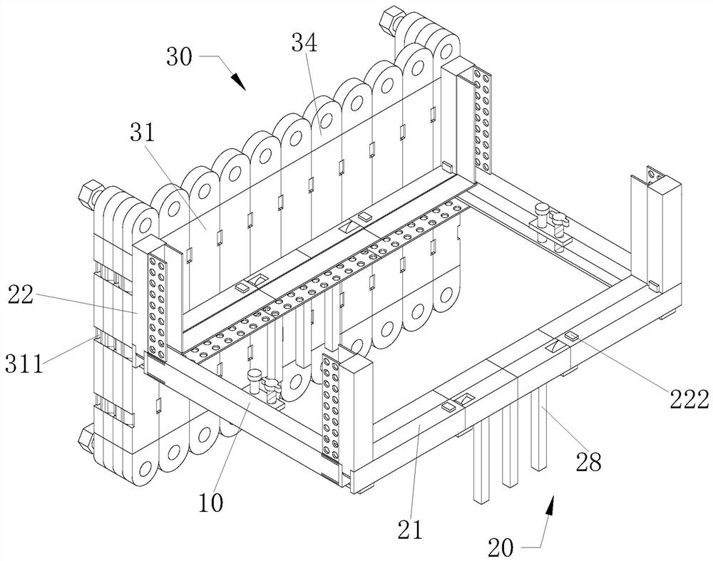
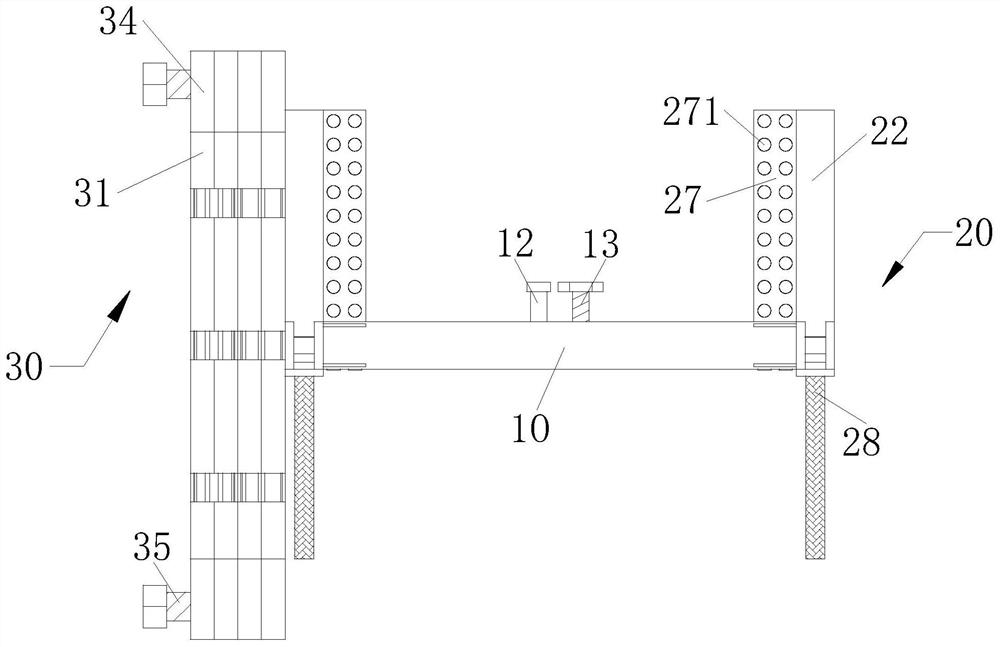
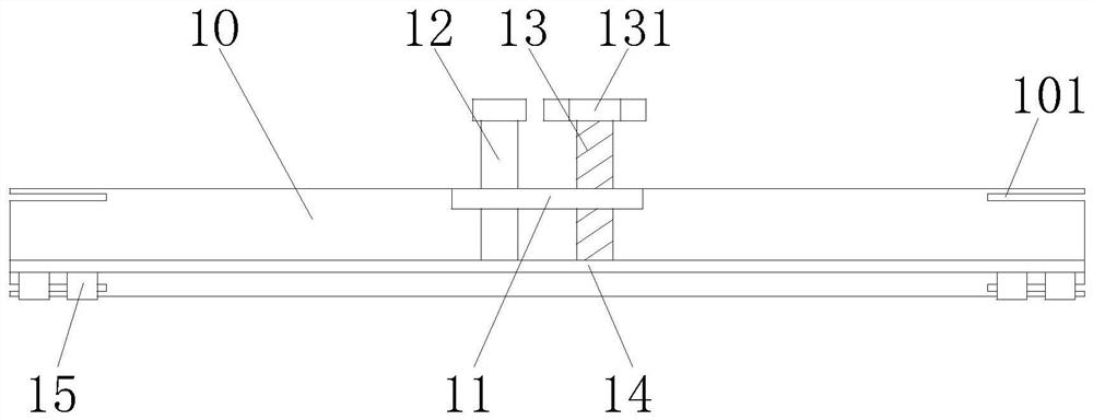
[0031] Such as Figure 1 to 9As shown, a building engineering foundation pit support steel template includes a rectangular steel frame 10 provided before and after, and the left and right ends of the rectangular steel frame 10 are symmetrically opened, the end surface of the moving groove 101 is rectangular, the mobile groove 101 extends in the longitudinal direction of the rectangular steel frame 10, and the moving groove 101 is symmetrically opened, and the width of the moving groove 101 is equal to the width of the rectangular steel frame 10, the side wall center between the two sets of rectangular steel frames A side stretch plate 11 is provided, and the top of the side extension plate 11 is rotated to the left end of the side extension plate 11, and the top of th...


PUM


Abstract

The invention relates to a construction engineering foundation pit supporting steel formwork. The construction engineering foundation pit supporting steel formwork comprises rectangular steel frames which are symmetrically arranged front and back; propping-up mechanisms are arranged on the outer sides of the two rectangular steel frames; and a supporting mechanism is arranged on the outer side of a first concave steel frame. Through cooperation of two-way screw rods, lifting plates, round pins and leakage holes, the two lifting plates can drive the round pins to move downwards under the threaded driving of the screw rods and the guiding effect of guiding rods and are inserted into the corresponding leakage holes for limiting, and the situation that the rectangular steel frames displace under the effect of external force, propping-up is not firm, and construction is affected is prevented; and in addition, through the design of the leakage holes, waste water and soil can be discharged easily, and the situation that when soil is accumulated between two clamping plates, the rectangular steel frames are inconvenient to install is prevented.

Description

Technical field [0001] The present invention relates to the field of building construction, and in particular, to a construction engineering foundation pit support steel template. Background technique [0002] The construction engineering major is mainly responsible for the teaching and management of civil engineering projects, mainly cultivating basic theories and basic knowledge of engineering mechanics, soil mechanics, measurement, housing architecture and structural engineering discipline. [0003] Foundation pit is the foundation design position according to the solar pit excaving the basis high and the basic plane size, the foundation pit support is to ensure the safety of underground structure and the safety of the foundation of the foundation pit, the support of the foundation pit side wall and the surrounding environment Block, reinforcement and protection measures. [0004] Steel template is also known as free template network, can replace the wood template, significant...

Claims


Application Information

Patent Timeline
IPC IPC(8): E02D17/04
CPCE02D17/04E02D2300/0029E02D2250/0007
Inventor 廖艳阳张在中
Owner 上海林伟建筑工程有限公司
Learn More