Underground mine raise boring machine

A technology for raise drilling rigs and mines, which is applied in earthwork drilling, drilling equipment, support devices, etc., which can solve problems such as inconvenient movement, achieve the effects of reducing labor costs, lightening the burden of transportation, and meeting the needs of use

Active Publication Date: 2021-06-15
NINGXIA TIANDI BENNIU IND GRP +1
View PDF11 Cites 1 Cited by
  • Summary
  • Abstract
  • Description
  • Claims
  • Application Information

AI Technical Summary

Problems solved by technology

[0005] Aiming at the deficiencies of the prior art, the present invention provides an underground mine raise drilling rig, which has the advantages of being easy to move, and solves the problem that common underground mine raise drilling rigs are not easy to move.

Method used


Image

  • Underground mine raise boring machine
  • Underground mine raise boring machine
  • Underground mine raise boring machine

Examples


Embodiment 1

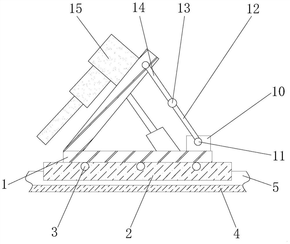
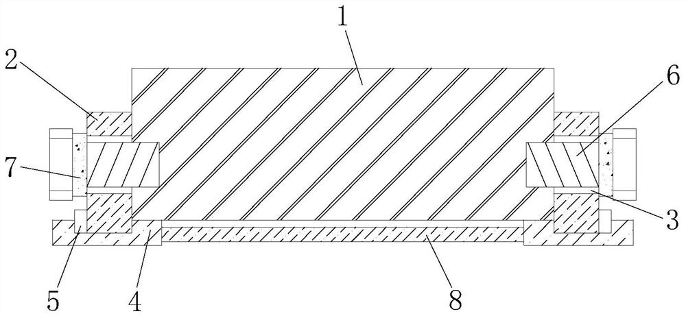
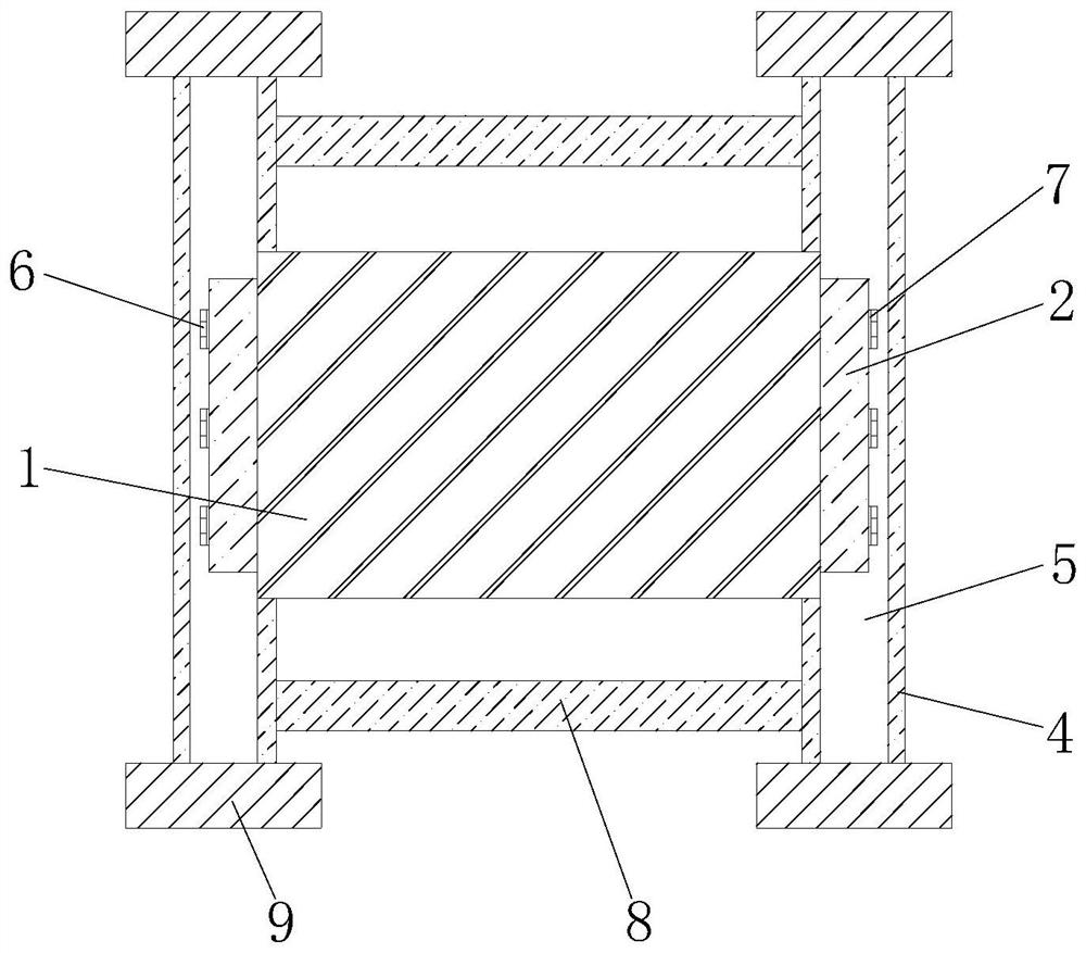
[0030] see Figure 1-3 , an underground mine raise drilling machine, comprising a base 1, the front of the base 1 is movably connected with a slider 2, the front of the slider 2 is provided with a fixing groove 3, the number of the fixing groove 3 is three, and the three fixing grooves 3 Equidistantly arranged on the front of the slider 2, the outer wall of the slider 2 is movably connected with a fixed plate 4, and the front of the fixed plate 4 is provided with a chute 5, and the shape and size of the slider 2 and the shape and size of the chute 5 are matched with each other. And the base 1 is movably connected with the chute 5 through the slider 2, the inner wall of the fixed groove 3 is movably connected with a bolt 6, the shape and size of the bolt 6 and the shape and size of the fixed groove 3 are all matched with each other, and the bolt 6 is connected with the sliding groove through the fixed groove 3. The block 2 is movably connected, and through the set fixing groove...

Embodiment 2

[0036] During the drilling operation, the broken cuttings are washed by the flushing fluid when the pilot hole is drilled, and the cuttings are lifted out of the borehole by the flushing fluid along the annular space between the drill pipe and the hole wall. The friction between the flushing fluid and the drill pipe can easily lead to poor slag discharge, and easily cause disturbance to the drill pipe, affecting the accuracy of drilling.

[0037] In order to solve the above-mentioned problems, the raise drilling machine provided by this embodiment also includes a friction-reducing drill pipe, refer to Figure 4 , the friction-reducing drill pipe includes: a rod body 110 , the inside of the rod body 110 is provided with a well-washing fluid flow path 111 arranged axially along the rod body 110 , and the outer surface of the rod body 110 is provided with a drag-reducing structure.

[0038] When working, the flushing fluid is output from the lower end of the rod body 110 through ...

Embodiment 3

[0051] refer to Figure 8 , On the basis of Embodiment 2, the friction-reducing drill pipe in this embodiment further includes a stabilizing ring 130 , the stabilizing ring 130 is sleeved on the rod body 110 , and the outer diameter of the stabilizing ring 130 is larger than the outer diameter of the rod body 110 .

[0052] When the flushing fluid flows through the stabilizing ring 130 from bottom to top, the circumferential turbulent flow in the stabilizing ring 130 forms a liquid gasket. When the friction-reducing drill pipe deviates, the turbulent flow on the compressed side of the liquid gasket is close to the hole wall, and the liquid pressure Increase to align the reduced-friction drill pipe.

[0053] Specifically, the lower surface of the stabilizing ring 130 and the connecting portion of the rod body 110 have an excessively circular arc. The resistance of the stabilizing ring 130 to the flushing fluid is reduced through the arc transition.

[0054] More specifically,...


PUM


Abstract

The invention relates to the technical field of underground mines, and discloses an underground mine raise boring machine. The underground mine raise boring machine comprises a base, wherein a sliding block is movably connected to the front surface of the base, fixing grooves are formed in the front surface of the sliding block, a fixing plate is movably connected to the outer wall of the sliding block, a sliding groove is formed in the front surface of the fixing plate, the inner walls of the fixing grooves are movably connected with bolts, and a transverse plate is fixedly connected with one side of the fixing plate. According to the underground mine raise boring machine, the purpose that the underground mine raise boring machine is convenient to move is achieved, so that the problem that a common underground mine raise boring machine is inconvenient to move is solved, people can conveniently translate the raise boring machine in the using process, the raise boring machine can be moved to a needed site for operation, and the carrying burden of the people is relieved, so that the labor cost of the people is reduced, the working efficiency of the people is improved, people use the raise boring machine more easily, the use requirements of the people are met, and convenience is brought to work of the people.

Description

technical field [0001] The invention relates to the technical field of underground mines, in particular to an underground mine raise drilling machine. Background technique [0002] Underground mines are production and business units that mine mineral resources by underground mining. The production process of an underground mine is that the ore body is excavated from the surface to access the ore body, and the ore body is divided into several stages or panels. blocks and stages. As we all know, people often use raise drilling rigs to mine underground mines. [0003] However, the existing underground mine raise drilling rigs are not easy to move, so that the raising drilling rig cannot be conveniently moved by people during use, and the raising drilling rig cannot be moved to the required site for operation, thereby increasing the number of people. The labor cost also reduces people's work efficiency, and it is not very worry-free for people to use, so the existing undergro...

Claims


Application Information

Patent Timeline
Patent Type & Authority Applications(China)
IPC IPC(8): E21B15/00
CPCE21B15/003
Inventor 张君王帆张彦禄刘红刚王宁刘庆华刘云王继国巩文黄庆学张乾一杨哲勇黄文东马晓孟庆良薛小虎杨海利孟国营
Owner NINGXIA TIANDI BENNIU IND GRP
Why Eureka
Try Eureka