Portable deployable parabolic antenna and folding and unfolding method

A parabolic antenna, portable technology, applied in the field of communication, can solve problems such as large size, and achieve the effect of convenient operation

Pending Publication Date: 2021-06-15
HARBIN INST OF TECH
View PDF0 Cites 2 Cited by
  • Summary
  • Abstract
  • Description
  • Claims
  • Application Information

AI Technical Summary

Problems solved by technology

[0004] However, most of the currently deployable parabolic antennas are vehicle-mounted or ship-borne systems driven by relatively large motors. Due to the limitations of large size and motor drive, additional equipment must be relied on for each deployment or deployment.

Method used


Image

  • Portable deployable parabolic antenna and folding and unfolding method
  • Portable deployable parabolic antenna and folding and unfolding method
  • Portable deployable parabolic antenna and folding and unfolding method

Examples


Embodiment Construction

[0024] The following will clearly and completely describe the technical solutions in the embodiments of the present invention with reference to the drawings in the embodiments of the present invention.

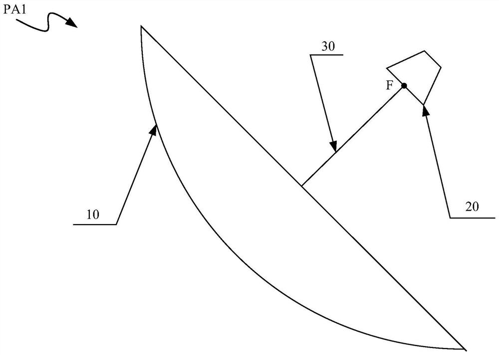
[0025] like figure 1 As shown, the parabolic antenna PA1 refers to a planar antenna composed of a parabolic reflector 10 and a feed 20 mounted on the reflector 10 through a feed bracket 30 and located at the focal point F of the reflector 10 . Generally, the reflector 10 adopts a metal rotating paraboloid, a cut rotating paraboloid or a cylindrical paraboloid, and the feed source 20 may adopt a horn feed source or a symmetrical vibrator feed source. When transmitting a signal, the signal radiates from the feed source 20 to the reflector 10 , and then radiates into the air after being reflected by the reflector 10 . Since the feed source 20 is located on the focal point F of the reflector 10, the electromagnetic wave is reflected by the reflector 10 and radiates parallel to th...


PUM


Abstract

An embodiment of the invention discloses a portable deployable parabolic antenna and a folding and unfolding method. The parabolic antenna comprises a fixed part, a plurality of ribs which are connected with the fixed part and are uniformly distributed in the circumferential direction of the parabolic antenna, a parabolic reflector, a feed source which is arranged on the focus of the reflector, a feed source bracket connected with the fixed part, and a movable part which is coaxially arranged with the fixed part, wherein the movable part sleeves the feed source bracket and can move towards the direction close to the fixed part in the length direction of the feed source bracket until the ribs are pressed tightly so that the parabolic antenna can be unfolded; or the movable part can move in the direction away from the fixed part along the length direction of the feed source bracket until the parabolic antenna can be completely folded.

Description

technical field [0001] The embodiments of the present invention relate to the technical field of communication, and in particular to a portable deployable parabolic antenna and a folding method. Background technique [0002] An antenna is a transformer used to transform a guided wave propagating on a transmission line into an electromagnetic wave propagating in an unbounded medium (usually free space), or vice versa. Antennas are components used to transmit or receive electromagnetic waves in radio equipment. Usually, electromagnetic waves are used to transmit information. Specifically, engineering systems such as radio communication, broadcasting, television, radar, navigation, electronic countermeasures, remote sensing, and radio astronomy are all Need to rely on the antenna to work. [0003] Antennas can be divided into line antennas and planar antennas according to their structural forms and working principles; and planar antennas can be further divided into plate anten...

Claims


Application Information

Patent Timeline
Patent Type & Authority Applications(China)
IPC IPC(8): H01Q1/08H01Q1/12H01Q19/12H01Q15/14
CPCH01Q1/08H01Q1/12H01Q15/14H01Q19/12
Inventor 胡超然曹喜滨冯宇斐张骥鹞韦明川郭金生王峰
Owner HARBIN INST OF TECH
Why Eureka
Try Eureka