
Power distribution cabinet with heat dissipation and fire extinguishing functions

A power distribution cabinet and functional technology, applied in the substation/distribution device casing, electrical components, substation/switch layout details, etc., can solve the problems of reduced heat dissipation effect, insufficient heat dissipation efficiency, damage, etc. Effect

Inactive Publication Date: 2021-06-15
谢满英
View PDF0 Cites 6 Cited by
  • Summary
  • Abstract
  • Description
  • Claims
  • Application Information

AI Technical Summary

Problems solved by technology

[0002] The current power distribution cabinet is the final equipment of the power distribution system. Its internal circuit structure is complex and generates a lot of heat. The existing power distribution cabinet usually has vents on both sides of the cabinet, and one of the two vents is used as an air inlet. , one is used as an air outlet, and a dust-proof net is installed at the vent to prevent dust, but there are the following defects: after a long time of use, the side of the dust-proof net facing the outside tends to adhere to or block the mesh, reducing the The air flow rate is reduced, and the heat dissipation effect is reduced; in order to prevent rainwater from gradually entering the cabinet through the vents, some power distribution cabinets are equipped with rain shields on the outside of the cabinet and on the upper side of the vents. If the heat dissipation equipment fails, it will lead to heat accumulation, which will cause a fire. At this time, the vents will continuously enter the oxygen, which is undoubtedly an accomplice to the fire. However, the existing cabinet can only call the police when it encounters a fire, and there are no fire extinguishing measures. , when the technician finds out and rescues it, it may have been completely damaged

Method used


Image

  • Power distribution cabinet with heat dissipation and fire extinguishing functions
  • Power distribution cabinet with heat dissipation and fire extinguishing functions
  • Power distribution cabinet with heat dissipation and fire extinguishing functions

Examples


Embodiment

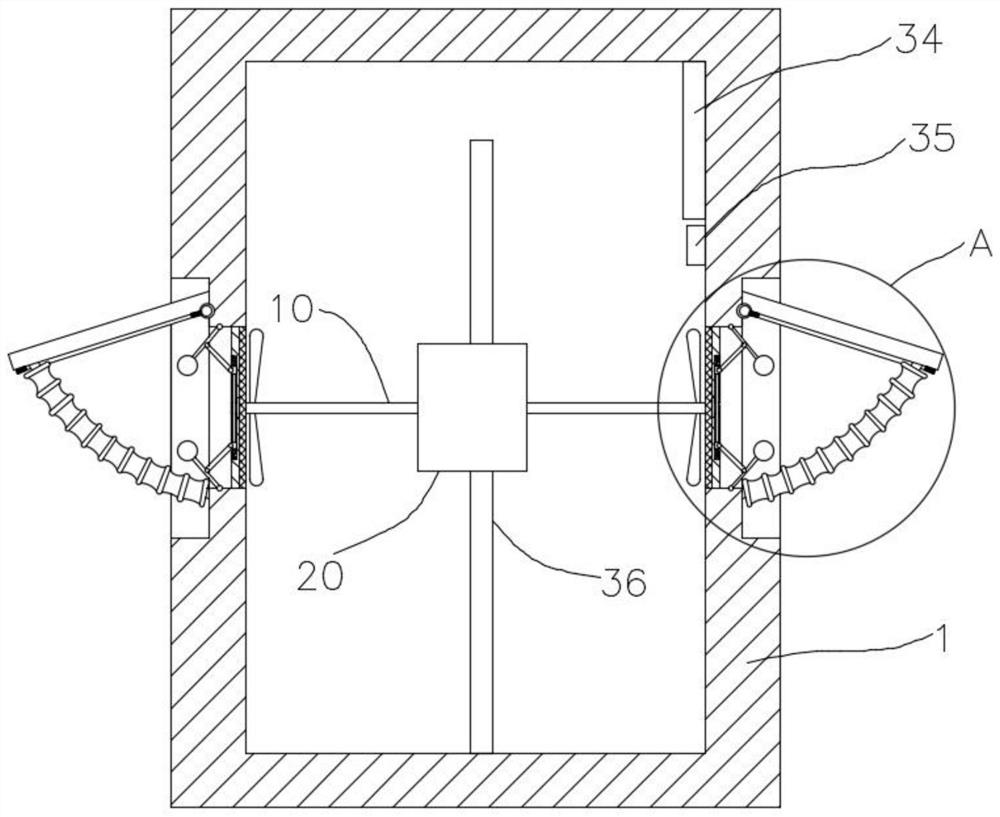
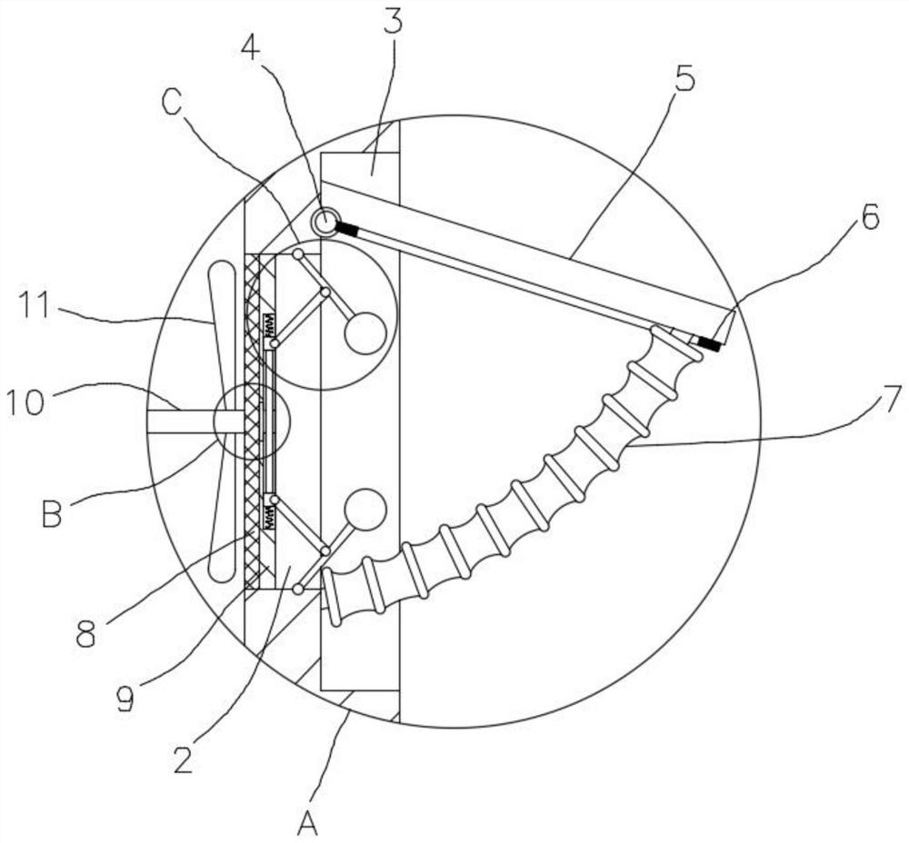
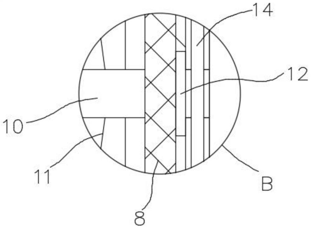
[0025] refer to Figure 1-5 , a power distribution cabinet with heat dissipation and fire extinguishing functions, including a cabinet body 1, and two sides of the cabinet body 1 are symmetrically provided with stepped vents, and the vents are composed of an inner vent 2 and an outer vent 3 that communicate from the inside to the outside The inner wall of the upper end of the outer vent 3 away from the inner vent 2 is rotated by the rotating shaft 4 to install a rain shield 5, and the rain shield 5 and the inner wall of the lower end of the outer vent 3 are jointly sealed and connected with an arc-shaped bellows 7, The bellows 7 forms an arc after inflation, and the side of the rain shield 5 near the inner vent 2 is glued and fixedly connected with a frame-shaped gasket 6 whose shape is larger than the inner vent 2, and the arc bellows 7 is connected with a release Air pipe, and a solenoid valve is installed on the air discharge pipe;

[0026] The inner wall of the inner air ...


PUM


Abstract

A power distribution cabinet with heat dissipation and fire extinguishing functions disclosed by the present invention comprises a cabinet body, stepped ventilation openings are symmetrically formed in the two sides of the cabinet body, each ventilation opening is composed of an inner ventilation opening and an outer ventilation opening which are communicated from inside to outside, and a flashing board is rotatably mounted on the inner wall of the upper end of the side, away from the inner ventilation opening, of the outer ventilation opening through a rotating shaft. The flashing board and the inner wall of the lower end of one side of the outer ventilation opening are jointly connected with an arc-shaped corrugated pipe in a sealed mode, the side, close to the inner ventilation opening, of the flashing board is fixedly connected with a frame-shaped sealing gasket in a glued mode, the sealing gasket is larger than the inner ventilation opening in shape and size, the arc-shaped corrugated pipe is connected with a deflation pipe, and an electromagnetic valve is installed on the deflation pipe. The power distribution cabinet has the advantages that one power source has multiple purposes, heat dissipation and vibration removal of impurities on meshes are separately carried out by flexibly utilizing the arrangement direction of the fan blades and the one-way bearing, in addition, the flashing board is opened through an arc-shaped corrugated pipe for heat dissipation or closed through the arc-shaped corrugated pipe for fire extinguishing, and creativity is high.

Description

technical field [0001] The invention relates to the technical field of power distribution cabinets, in particular to a power distribution cabinet with the function of heat dissipation and fire extinguishing. Background technique [0002] The current power distribution cabinet is used as the final equipment of the power distribution system. Its internal circuit structure is complex and generates a lot of heat. The existing power distribution cabinet usually has vents on both sides of the cabinet, and one of the two vents is used as an air inlet. , one is used as an air outlet, and a dust-proof net is installed on the vent to prevent dust, but it has the following defects: after a long time of use, the side of the dust-proof net facing the outside tends to adhere to or block the mesh, reducing the The air flow rate is reduced, and the heat dissipation effect is reduced; in order to prevent rainwater from gradually entering the cabinet through the vents, some power distribution...

Claims


Application Information

Patent Timeline
Patent Type & Authority Applications(China)
IPC IPC(8): H02B1/30H02B1/28H02B1/56
CPCH02B1/28H02B1/30H02B1/306H02B1/565
Inventor 谢满英
Owner 谢满英
Learn More