Supercharge Your Innovation With Domain-Expert AI Agents!

An Internet-based remote monitoring intelligent switchgear

A remote monitoring and intelligent switch technology, applied in the field of switch cabinets, can solve the problems of inability to comprehensively remove dust, low efficiency, and manual dust removal in switch cabinets.

Active Publication Date: 2021-10-12
合肥华创电气技术有限公司
View PDF1 Cites 0 Cited by
  • Summary
  • Abstract
  • Description
  • Claims
  • Application Information

AI Technical Summary

Problems solved by technology

[0002] The switchgear is a kind of equipment used for power transmission, power generation and electric energy conversion in the power system. However, the existing switchgear is easy to attract dust due to its electrification characteristics, which affects its performance. The dust removal of the switchgear is manual and the efficiency is low.
[0003] There are also some technical solutions about switch cabinets in the prior art. For example, the Chinese patent application number CN201910484305.7 discloses a switch cabinet for intelligent dust removal, including a switch cabinet. Dust removal tank, the dust removal tank is provided with a dust removal mechanism, the dust removal mechanism includes a dust removal block located in the dust removal tank, the left end of the dust removal block is fixed with a dust removal bag whose left end is located outside, and the dust removal block is equipped with There are dust suction grooves running through the left and right end walls of the dust removal block; the dust removal structure in this scheme is relatively complicated, and at the same time, during the dust removal process, only the dust attached to the fixed area in the switch cabinet can be cleaned, and the switch cabinet cannot be completely removed The dust entering from the outside in the cabinet is easy to cause dust to accumulate in the corners of the cabinet, which will eventually affect the normal operation of the electrical components in the cabinet and cause safety hazards

Method used


Image

  • An Internet-based remote monitoring intelligent switchgear
  • An Internet-based remote monitoring intelligent switchgear
  • An Internet-based remote monitoring intelligent switchgear

Examples


Embodiment approach

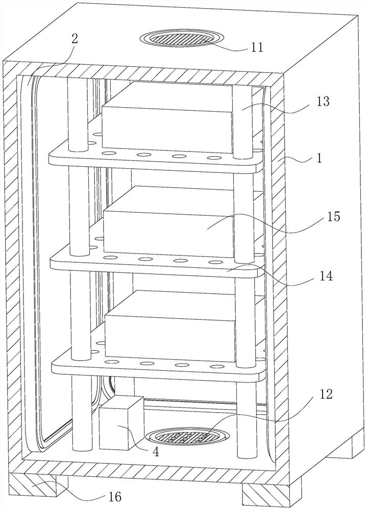
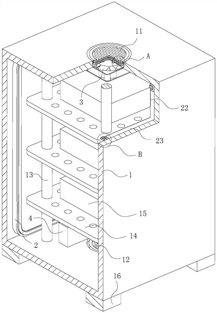
[0042] As an embodiment of the present invention, the film 22 includes an outer film 222 and an inner film 223; the outer film 222 and the inner film 223 are prepared by multi-layer co-extrusion, and the outer film 222 and the inner film The layer film 223 is made of PET material; the inner layer film 223 is evenly mixed with 10-15% graphene in the raw material during the preparation process; the distance between the inner layer film 223 and the inner wall of the cabinet body 1 Less than the distance between the outer film 222 and the inner wall of the cabinet body 1;

[0043] During operation, due to the influence of the electric field and magnetic field generated by the electrical components 15 in the cabinet 1 during normal operation, the film 22 on the inner wall of the cabinet 1 tends to accumulate static electricity, causing dust and other impurities entering the cabinet 1 to pass through. The electrostatic effect is adsorbed on the inner wall of the cabinet body 1. Afte...


PUM


Abstract

The invention belongs to the technical field of switch cabinets, in particular to an Internet-based remote monitoring type intelligent switch cabinet, comprising a cabinet body and a cabinet door, and the cabinet door is hingedly installed on the cabinet body; the lower surface of the cabinet body is fixed on the cabinet body feet are installed; vertical rods are fixedly installed in the cabinet, and installation plates are fixedly installed on the vertical rods; electrical components are fixedly installed on the installation plates; air outlets are respectively provided on the upper and lower end surfaces of the cabinet body and an air inlet; a filter screen is fixedly installed at the air inlet and the air outlet; a fan is fixedly installed on the upper surface of the cabinet body; an ultrasonic generator is fixedly installed on the bottom surface of the cabinet body; the A fixing seat is fixedly installed on the side wall of the cabinet; an extrusion groove is opened on the fixing seat, and an extrusion block is fixedly installed in the extrusion groove; a film is fixedly installed on the fixing seat through the extrusion block; The invention has a simple structure, has good cleaning effect on dust in the switch cabinet, and will not damage the parts in the cabinet.

Description

technical field [0001] The invention belongs to the technical field of switch cabinets, in particular to an Internet-based remote monitoring intelligent switch cabinet. Background technique [0002] The switchgear is a kind of equipment used for power transmission, power generation and electric energy conversion in the power system. However, the existing switchgear is easy to attract dust due to its electrification characteristics, which affects its performance. The dust removal of the switchgear is manual and the efficiency is low. . [0003] There are also some technical solutions about switch cabinets in the prior art. For example, the Chinese patent application number CN201910484305.7 discloses a switch cabinet for intelligent dust removal, including a switch cabinet. Dust removal tank, the dust removal tank is provided with a dust removal mechanism, the dust removal mechanism includes a dust removal block located in the dust removal tank, the left end of the dust remov...

Claims


Application Information

Patent Timeline
Patent Type & Authority Patents(China)
IPC IPC(8): H02B1/56H02B1/28H02B1/32B01D46/00B01D46/10A62C3/16A62C35/10
CPCH02B1/565H02B1/28H02B1/32B01D46/10A62C3/16A62C35/10B01D46/76
Inventor 黄劲程家龙
Owner 合肥华创电气技术有限公司
Features
  • R&D
  • Intellectual Property
  • Life Sciences
  • Materials
  • Tech Scout
  • Unparalleled Data Quality
  • Higher Quality Content
  • 60% Fewer Hallucinations
Learn More