Rotor assembly and self-starting permanent magnet synchronous reluctance motor

A rotor and assembly technology, applied in synchronous machine parts, electric components, magnetic circuit rotating parts, etc., can solve problems such as high cost, reduced motor output torque and efficiency, and complex control

Inactive Publication Date: 2021-06-15
GREE ELECTRIC APPLIANCES INC
View PDF10 Cites 1 Cited by
  • Summary
  • Abstract
  • Description
  • Claims
  • Application Information

AI Technical Summary

Problems solved by technology

[0003] Traditional permanent magnet motors and permanent magnet synchronous reluctance motors require a driver to start and control the operation, which is costly and complicated to control, and the driver occupies a part of the loss, which reduces the efficiency of the entire motor system
[0004] The Chinese invention patent with the patent publication number CN107994698A provides a self-starting permanent magnet synchronous reluctance motor to reduce the cost of the permanent magnet. However, the end squirrel cage groove (d-axis squirrel cage groove) in this patent is a long arc groove, which hinders The d-axis magnetic flux of the permanent magnet is reduced, and the permanent magnet torque is reduced; in addition, the ends of the magnetic conduction channels between the magnets all extend toward the q-axis, so that the magnetic conduction channels gradually narrow along the extension direction of the q-axis, thus making the stator q-axis Higher saturation reduces the output torque and efficiency of the motor

Method used


Image

  • Rotor assembly and self-starting permanent magnet synchronous reluctance motor
  • Rotor assembly and self-starting permanent magnet synchronous reluctance motor
  • Rotor assembly and self-starting permanent magnet synchronous reluctance motor

Examples


Embodiment Construction

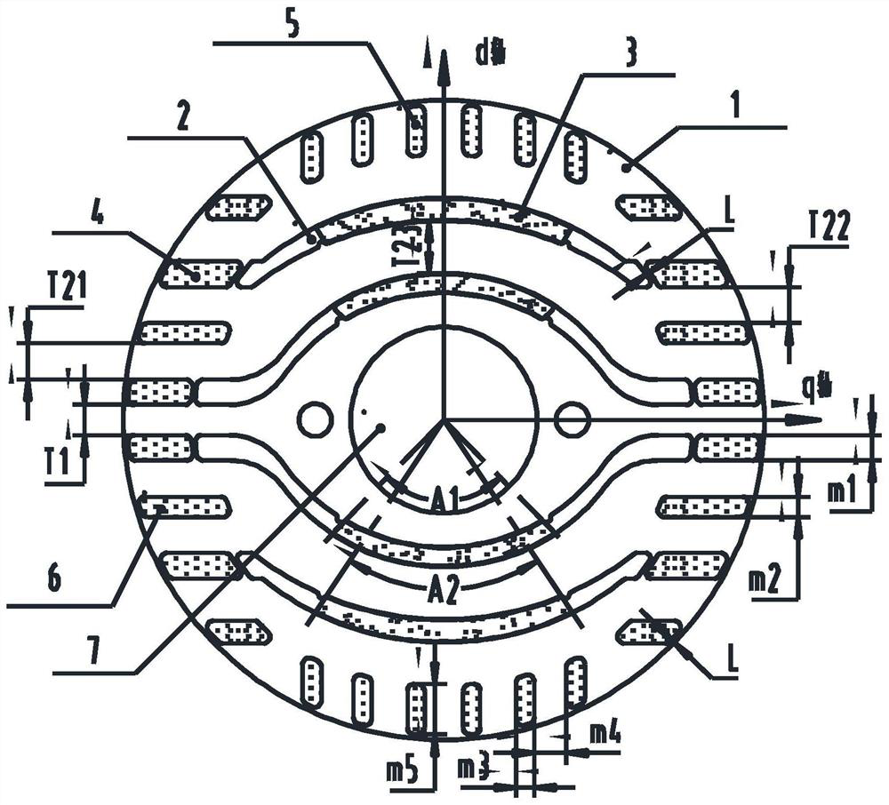
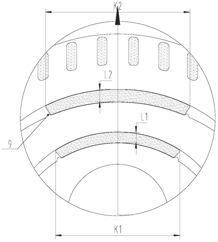
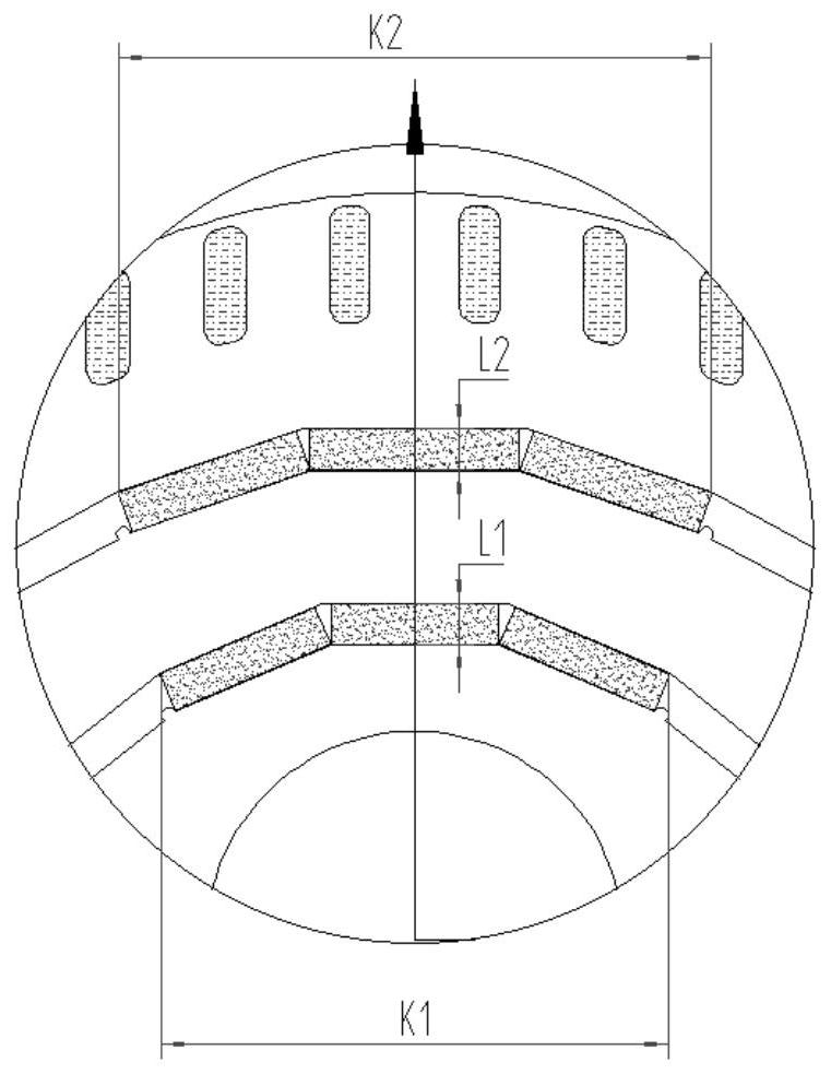
[0032] see in conjunction Figure 1 to Figure 7 As shown, according to the embodiment of the present application, the rotor core 1 is included. On the cross section of the rotor core 1, the rotor core 1 is provided with a shaft hole 7, a slit slot 2, a q-axis squirrel cage slot 4, an independent The squirrel cage 6, the d-axis squirrel cage 5 and the permanent magnet 3, the q-axis squirrel cage 4 are located at both ends of the slit 2, and the independent squirrel cage 6 is set in a misalignment with the slit 2 along the d-axis direction, and the d-axis There are multiple squirrel-cage slots 5, and they are located on the side of the slit slot 2 close to the outer circle of the rotor. The d-axis squirrel-cage slot 5 is set close to the d-axis relative to the q-axis squirrel-cage slot 4 and the independent squirrel-cage slot 6. The permanent magnet 3 Installed in the slit groove 2, the extension direction of the q-axis cage groove 4 and the independent cage groove 6 is parallel...


PUM


Abstract

The invention provides a rotor assembly and a self-starting permanent magnet synchronous reluctance motor. The rotor assembly comprises a rotor core (1), on the cross section of the rotor core (1), the rotor core (1) is provided with slit grooves (2), q-axis squirrel cage grooves (4), independent squirrel cage grooves (6), d-axis squirrel cage grooves (5) and permanent magnets (3), the extension directions of the q-axis squirrel cage grooves (4) and the independent squirrel cage grooves (6) are parallel to the q-axis, and the d-axis squirrel cage grooves (5) extend in the direction parallel to the d-axis or extend in the radial direction of the rotor core (1). According to the rotor assembly provided by the invention, the q-axis magnetic flux can be increased, and meanwhile, the permanent magnet magnetic flux can smoothly enter the stator through the d axis, so that the permanent magnet torque and efficiency of the motor are improved.

Description

technical field [0001] The present application relates to the technical field of motors, in particular to a rotor assembly and a self-starting permanent magnet synchronous reluctance motor. Background technique [0002] The self-starting permanent magnet synchronous reluctance motor combines the structural characteristics of the induction motor and the synchronous permanent magnet reluctance motor. The starting torque is generated by the squirrel cage induction, and the constant torque is realized by the difference between the d and q axis magnetic flux of the rotor and the torque generated by the permanent magnet. It can run at high speed and can be directly connected to the power supply to realize the starting operation. The self-starting permanent magnet synchronous reluctance motor can use the reluctance torque to increase the output torque of the motor. Compared with the self-starting permanent magnet motor, the amount of permanent magnets is reduced and the cost is red...

Claims


Application Information

Patent Timeline
Patent Type & Authority Applications(China)
IPC IPC(8): H02K1/27H02K21/02
CPCH02K1/27H02K1/272H02K21/02H02K2213/03
Inventor 胡余生陈彬肖勇史进飞李霞张志东
Owner GREE ELECTRIC APPLIANCES INC
Why Eureka
Try Eureka