
Dish washing machine with compact structure

A compact and dishwasher-safe technology, applied to tableware washing machines/rinsing machines, tableware washing machines/rinsing and rinsing machine parts, cleaning equipment, etc., can solve the problems of complex waterway design and high cost, and achieve assembly and manufacturing The effect of low process cost, low manufacturing cost and compact design

Inactive Publication Date: 2021-06-18
周欢
View PDF8 Cites 0 Cited by
  • Summary
  • Abstract
  • Description
  • Claims
  • Application Information

AI Technical Summary

Problems solved by technology

But at the same time, the design of the waterway in the top wall of the cavity or the surrounding walls is relatively complicated, and the cost of the complete machine assembly is relatively high

Method used


Image

  • Dish washing machine with compact structure
  • Dish washing machine with compact structure
  • Dish washing machine with compact structure

Examples


Embodiment 1

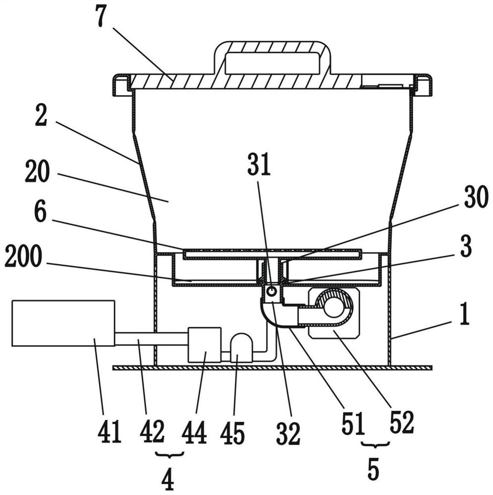
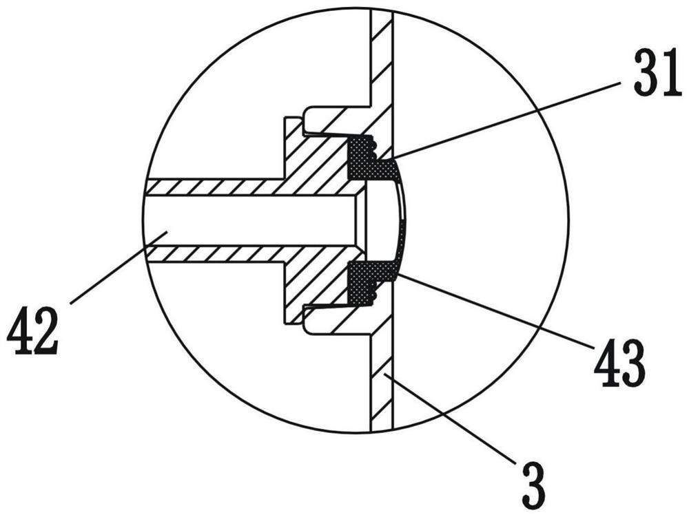
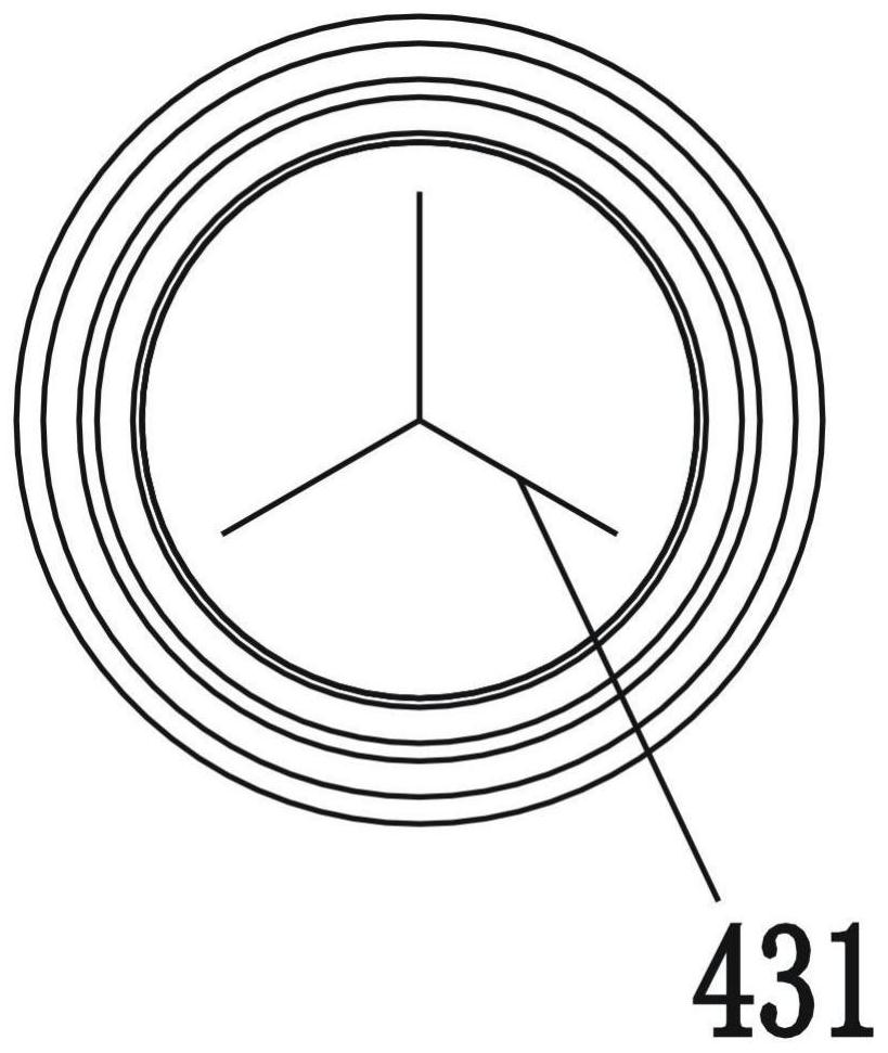
[0036] like figure 1 , figure 2 , image 3 As shown, it is a schematic structural diagram of an embodiment of the dishwasher of the present invention. A dishwasher, comprising a base 1 and a housing 2 mounted above the base 1, a cleaning chamber 20 is formed in the housing 2, and an opening communicating with the cleaning chamber 20 is provided on the upper end of the housing 2, And the cover body 7 is sealed and installed at the opening. Wherein, the bottom of the cleaning chamber 20 is provided with a water collecting tank 200, the bottom of the cleaning chamber 20 is provided with a hollow spray seat 3, and the water outlet 30 of the spray seat 3 is located in the cleaning chamber 20, and sprays The lower part of the shower seat 3 extends into the base 1, the lower part of the shower seat 3 has a first water inlet hole 31 and a second water inlet hole 32, the first water inlet hole 31 is communicated with the water supply system 4, and the first water inlet hole 31 is ...

Embodiment 2

[0042] like Figure 7 , Figure 8 As shown, it is a schematic structural diagram of the second embodiment of the present invention. The difference between this embodiment and the first embodiment is that: in this embodiment, the casing 2 is a foldable structure, which includes a foldable connecting ring 22 and a support ring 23 fixed on the upper end of the connecting ring 22 . The body 2 can be folded through the connecting ring 22. At the same time, in this embodiment, the connecting ring 22 has a structure of large upper and lower small, and the connecting ring 22 includes a hard ring 221 and a flexible ring 222, wherein the hard ring 221 It is integrally formed with the flexible ring 222 .

[0043] At the same time, in this embodiment, an isolation plate 13 is arranged in the base 1, and the isolation plate 13 divides the space in the base 1 into an installation cavity 14 and a water holding cavity 15, wherein the circulating water pump 52, the water pump 44, and the flo...


PUM


Abstract

The invention relates to a kitchen cleaning electric appliance and particularly relates to a dishwasher with a compact structure. The dishwasher comprises a base and a shell arranged above the base, wherein a cleaning chamber is formed in the shell, and a water collecting tank is arranged at the bottom of the cleaning chamber, and is characterized in that a hollow spraying seat is arranged at the bottom of the cleaning chamber; a water outlet end of the spraying base is located in the cleaning cavity, a lower portion of the spraying base extends into the base, a first water inlet hole and a second water inlet hole are formed in the lower portion of the spraying base, the first water inlet hole is communicated with a water supply system, and the second water inlet hole is communicated with a water collecting tank through a circulating system; the water supply system and the circulating system feed water into the cleaning cavity through a water outlet end of the spraying base, and the water supply system and the circulating system do not work at the same time. The dishwasher is advantaged in that the water inlet and the circulating outlet of the dish-washing machine are the same port, the waterway design is greatly simplified, the overall structure is more compact, and the cost is lower.

Description

technical field [0001] The present invention relates to kitchen cleaning appliances, in particular to a dishwasher with a compact structure. Background technique [0002] The existing dishwashers on the market are generally divided into two types. One is the built-in dishwasher that is embedded in the wall or in the sink. This type of dishwasher needs to be installed by professionals and does not take up space after being embedded. For a small user group, the kitchen space is greatly saved, but for the consumer group who has no fixed residence and often moves, this kind of dishwasher is obviously not suitable. The other is a desktop dishwasher that can be placed on the countertop. The desktop dishwasher can be placed in the kitchen space, or in the living room, balcony and other spaces. It is not affected by the placement space, and can also be placed with the user's furniture. Relocation, however, the dishwasher is bulky and heavy, which is troublesome to relocate, and tak...

Claims


Application Information

Patent Timeline
Patent Type & Authority Applications(China)
IPC IPC(8): A47L15/14A47L15/42
CPCA47L15/14A47L15/4217A47L15/4251A47L15/4278
Inventor 周欢
Owner 周欢
Learn More