
A kind of self-cleaning device for gluing nitrile gloves

A nitrile glove, self-cleaning technology, applied in the direction of spray device, device for coating liquid on the surface, coating, etc., can solve the problem of affecting the purity of glue in the dipping tank, improve the cleaning effect and facilitate the The effect of uniformity and not easy precipitation of colloids

Active Publication Date: 2021-09-07
阜阳市茂泰商贸有限公司
View PDF10 Cites 0 Cited by
  • Summary
  • Abstract
  • Description
  • Claims
  • Application Information

AI Technical Summary

Problems solved by technology

[0004] However, in the actual use process, the inventor found that when the dipping tank body is performing gluing work, the colloid will adhere to the inner wall of the dipping tank tank, which needs to be shut down for cleaning, and at the same time affects the purity of the glue in the dipping tank tank The problem

Method used


Image

  • A kind of self-cleaning device for gluing nitrile gloves
  • A kind of self-cleaning device for gluing nitrile gloves
  • A kind of self-cleaning device for gluing nitrile gloves

Examples


Embodiment 1

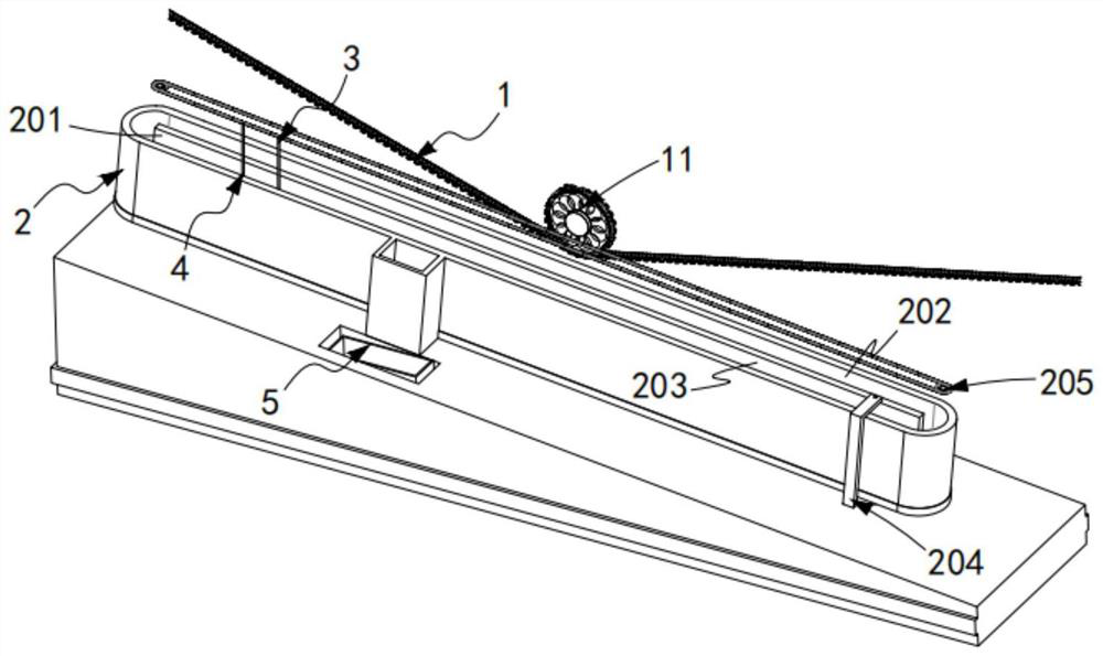
[0076] Such as figure 1 Shown, a kind of nitrile glove self-cleaning device for gluing, comprising:

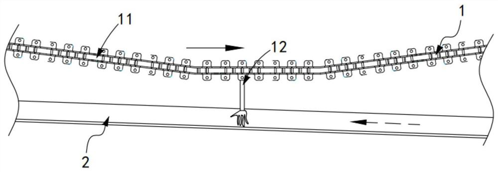
[0077] A glove transmission mechanism 1, the glove transmission mechanism 1 includes a transmission unit 11 and several groups of glove molds 12 arranged on the transmission unit 11 at equal intervals;

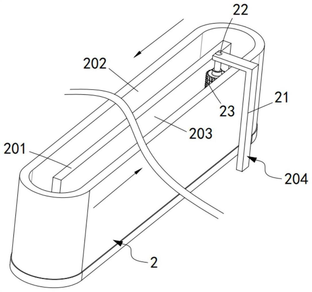
[0078] The dipping tank body 2, the dipping tank body 2 is arranged obliquely downward and is located below the transmission unit 11, the dipping tank body 2 is arranged in an elliptical structure, along the A partition plate 201 arranged in the middle of the body 2 and along the length direction of the dipping tank body 2 , a gluing space 202 and an impurity discharge space 203 are formed between the dipping tank body 2 and the partition plate 201 ;

[0079] The transmission mechanism 204, the transmission mechanism 204 is arranged at the lower end part of the dipping tank body 2 and is located in the impurity discharge space 203;

[0080] Chain-moving mechanism 205, the c...

Embodiment 2

[0120] Such as Figure 15 to Figure 20 As shown, the components that are the same as or corresponding to those in the first embodiment are marked with the corresponding reference numerals in the first embodiment. For the sake of simplicity, only the differences from the first embodiment will be described below. The difference between this embodiment two and embodiment one is:

[0121] further, such as Figure 15 to Figure 20 As shown, the first discharge assembly 51 includes:

[0122] A flat-push cylinder 511, the telescopic end of the flat-push cylinder 511 is arranged vertically downward, and its lower end is fixedly provided with a telescopic unit a512;

[0123] A limit plate 513, the limit plate 513 is fixedly connected to the lower end of the telescopic unit a512 and set to match the width of the impurity discharge space 203, the limit plate 513 is set for the filter mesh structure;

[0124] The push-out cylinder 514, the push-out cylinder 514 is made of elastic rubber...


PUM


Abstract

The invention relates to a self-cleaning device for gluing nitrile gloves, comprising a glove transmission mechanism; A partition plate arranged along the length direction of the dipping tank body, a gluing space and an impurity discharge space are formed between the dipping tank body and the partition plate; a transmission mechanism; a chain mechanism, the The chain mechanism and the transmission mechanism work synchronously through the linkage mechanism; the first cleaning mechanism; the second cleaning mechanism; the first impurity collection mechanism, the first impurity collection mechanism includes a first discharge assembly and a first collection assembly ; and the second impurity collection mechanism, which includes a switching assembly and a second collection assembly; the present invention solves the problem that when the dipping tank body is performing gluing work, the colloid will adhere to the inner wall of the dipping tank, and it needs to be shut down for cleaning , and at the same time affect the technical problems of the purity of the glue in the dipping tank.

Description

technical field [0001] The invention relates to the technical field of nitrile gloves, in particular to a self-cleaning device for gluing nitrile gloves. Background technique [0002] Nitrile latex is a kind of latex with larger polarity. The nitrile rubber formed after curing has excellent water resistance, oil resistance and chemical corrosion resistance, so it is more and more widely used in the preparation of gloves and the like. However, the surface of nitrile rubber is relatively flat and smooth, and it becomes smoother when it meets water or oil. When it is used as a protective glove, its anti-skid effect is poor, which limits the application function of nitrile gloves. For this reason, the industry usually creates textures on the surface of nitrile gloves to increase the anti-slip effect. However, nitrile latex has better oil resistance, and it is difficult to use chemical methods to create lines. [0003] The patent document whose patent number is CN2018109805019 ...

Claims


Application Information

Patent Timeline
Patent Type & Authority Patents(China)
IPC IPC(8): B05C3/10B05C13/02B05B15/50
CPCB05C3/10B05C13/02B05B15/50
Inventor 龚贝娜
Owner 阜阳市茂泰商贸有限公司
Learn More