
Belt winding and arranging device

A technology of belt unscrambling and fixing seat, which is applied in the directions of coiling strips, thin material handling, transportation and packaging, etc. It can solve the problems of pinch roll flattening, complex structure, and increased equipment manufacturing cost.

Pending Publication Date: 2021-06-18
丁文煜
View PDF0 Cites 0 Cited by
  • Summary
  • Abstract
  • Description
  • Claims
  • Application Information

AI Technical Summary

Problems solved by technology

The traditional way is usually manually wound, the winding efficiency is low, the labor cost is high, and when winding, the belt will appear spiral twist, people need to flatten it by hand, the winding operation is troublesome, so people invented Automatic tape winding machine. In order to automatically arrange and level the tape during the winding process, the existing automatic tape winding machine usually sets two nip rollers and multiple guide rollers at the input end of the tape. The gap between the two nip rollers is less than The thickness of the belt, the belt is automatically leveled through the gap, and then tightened by multiple guide rollers, but this structure is only suitable for the belt with a slightly harder winding material. If the material of the belt is soft and has a certain degree of elasticity, it is spiral When the twisted belt passes through the two nip rollers, the helically twisted belt is easily pinched and flattened by the nip rollers directly, and even the belt is stuck in the position of the nip rollers. If the machine continues to run, the belt will be broken, and the structure is complicated , which increases the manufacturing cost of the equipment

Method used


Image

  • Belt winding and arranging device
  • Belt winding and arranging device
  • Belt winding and arranging device

Examples


Embodiment Construction

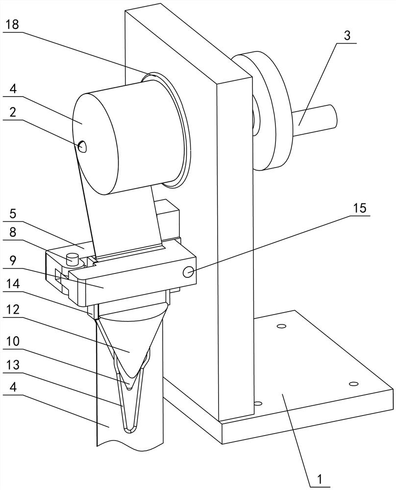
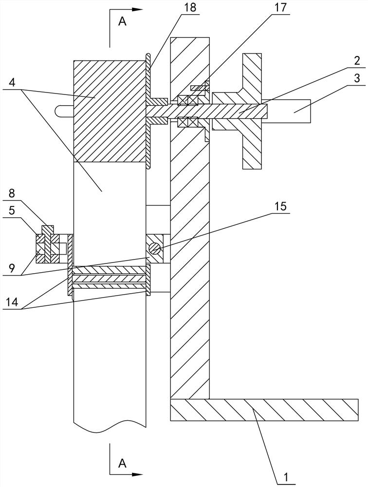
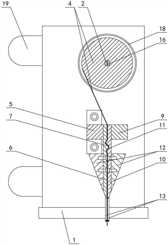
[0020] The invention relates to a tape unwinding device, such as figure 1 — Image 6 As shown, it includes a fixed seat 1, a rotating shaft 2 is arranged in the fixed seat, one end of the rotating shaft is connected to the rocker 3, and the other end of the rotating shaft passes through the fixed seat to cooperate with the belt 4 to be wound, and one side of the fixed seat 1 is set Fixed entrainment seat 5, the fixed entrainment seat is fixed with the fixed seat through fasteners, the fixed entrainment seat is provided with a fixed tape head 6, the top of the fixed tape head is fixed with the fixed entrainment seat, and the inner wall of the fixed tape head is shaped on the first wave Shape lines 7, the lower part of the fixed tape head is conical, one side of the fixed entrainment seat 5 is connected to the rotating entrainment seat 9 through the pin 8, the other side of the rotating entrainment seat cooperates with the fixed entrainment seat through the locking structure, an...


PUM


Abstract

The invention relates to a belt winding and arranging device which comprises a fixing seat. A rotating shaft is arranged in the fixing seat, one end of the rotating shaft is connected with a rocking handle, the other end of the rotating shaft penetrates through the fixing seat so as to be matched with a belt to be wound, a fixing belt clamping seat is arranged on one side of the fixing seat and fixed with the fixing seat through a fastener, a fixing belt arranging head is arranged on the fixing belt clamping seat, the upper part of the fixing belt arranging head is fixed to the fixing belt clamping seat, first wavy lines are manufactured on the inner wall of the fixing belt arranging head, the lower part of the fixing belt arranging head is conical, one side of the fixing belt clamping seat is connected with a rotating belt clamping seat through a pin, the other side of the rotating belt clamping seat is matched with the fixing belt clamping seat through a locking structure, a rotating belt arranging head is arranged on the rotating belt clamping seat, the upper part of the rotating belt arranging head is fixed to the rotating belt clamping seat, second wavy lines are arranged on the inner wall of the rotating belt arranging head and correspond to the first wavy lines, and the lower part of the rotating belt arranging head is conical.

Description

technical field [0001] The invention relates to a tape unwinding device. Background technique [0002] Various belts are often used in daily life, such as straps, belts, bandages, etc., and some belts are long in length and will be used repeatedly. After use, they need to be wound up for storage, or in production After it is manufactured, it needs to be wound and packaged. The traditional way is usually manually wound, the winding efficiency is low, the labor cost is high, and when winding, the belt will appear spiral twist, people need to flatten it by hand, the winding operation is troublesome, so people invented Automatic tape winding machine. In order to automatically arrange and level the tape during the winding process, the existing automatic tape winding machine usually sets two nip rollers and multiple guide rollers at the input end of the tape. The gap between the two nip rollers is less than The thickness of the belt, the belt is automatically leveled through the...

Claims


Application Information

Patent Timeline
IPC IPC(8): B65H18/02B65H18/10B65H23/188B65H23/34B65H75/28B65H19/28B65H19/30
CPCB65H18/02B65H18/10B65H19/28B65H19/30B65H23/1888B65H23/34B65H75/28B65H2701/11332
Inventor 丁文煜
Owner 丁文煜
Learn More