Film forming method and film forming apparatus

A film-forming method and a film-forming device technology, which are applied in the direction of ion implantation plating, coating, metal material coating process, etc., can solve the problems of different film forming rates, inability to obtain functions, quality, film thickness differences, etc.

Pending Publication Date: 2021-06-18
CANON TOKKI CORP
View PDF8 Cites 0 Cited by
  • Summary
  • Abstract
  • Description
  • Claims
  • Application Information

AI Technical Summary

Problems solved by technology

In this way, if the pores V are formed, the desired function and quality may not be obtained.
The cause of the voids in this way is that the film formation rate differs depending on the upper surface of the concave portion, the upper surface of the convex portion, and the side surface of the substrate where the particles are adhered by sputtering, resulting in a difference in the film thickness.

Method used


Image

  • Film forming method and film forming apparatus
  • Film forming method and film forming apparatus
  • Film forming method and film forming apparatus

Examples


Embodiment approach

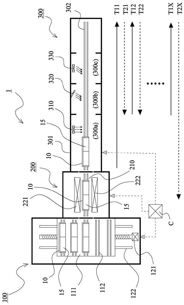
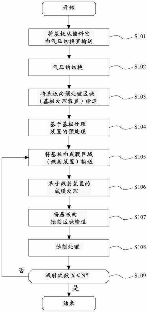
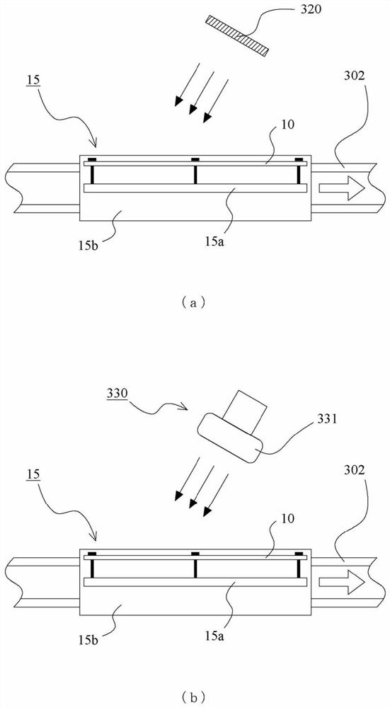
[0035] refer to Figure 1 to Figure 9 , the film forming method and the film forming apparatus according to the embodiment of the present invention will be described. figure 1 It is a schematic configuration diagram of the interior of the film formation apparatus according to the embodiment of the present invention, and shows a schematic configuration when the entire interior of the film formation apparatus is viewed from above. figure 2 It is a flowchart showing the operation of the film forming apparatus according to the embodiment of the present invention. image 3 It is an explanatory diagram of the operation of the film forming apparatus according to the embodiment of the present invention. Figure 4 It is a schematic configuration diagram of the inside of the film forming apparatus according to the embodiment of the present invention, and shows a schematic configuration of the vicinity where the etching apparatus is installed as viewed along the conveying direction of...


PUM


Abstract

The present invention provides a film forming method and a film forming apparatus, which can cover a surface with a predetermined film thickness while maintaining a concave-convex surface shape when forming a thin film on the surface of a substrate on which a convex part and a concave part are formed. The film forming method forms a film on a substrate (10) in which the convex part extending in a first direction and the concave part extending in the first direction are alternately formed in a second direction intersecting the first direction. The film forming method is characterized by comprising: a film forming step for forming a thin film by irradiating the substrate (10) with a film forming material; and an etching step in which the substrate (10) on which the thin film is formed is irradiated with an etching beam and etched, the direction in which the film-forming material is irradiated and the direction in which the etching beam is irradiated are inclined with respect to the normal line of the film-forming surface of the substrate (10), wherein the irradiation angles of both are set to be the same.

Description

technical field [0001] The invention relates to a film forming method and a film forming device for forming a thin film on a substrate. Background technique [0002] Conventionally, a technique of forming a thin film on a substrate by sputtering or the like is known. However, when unevenness is provided on the surface of the substrate, cavities called voids may be formed inside the formed thin film. On this point, see Figure 10 Be explained. Figure 10 It is a schematic cross-sectional view of a substrate on which a thin film is formed by a conventional film-forming method. [0003] Protrusions 711 and recesses 712 are provided on the surface of the illustrated substrate 710 . Figure 10 (a) shows the initial state during the film-forming process. As shown in the figure, the formed film 720a is formed so that a part of the film formed on the upper surface of the convex portion 711 protrudes toward the concave portion 712 and covers it. Therefore, if the film formation pr...

Claims


Application Information

Patent Timeline
Patent Type & Authority Applications(China)
IPC IPC(8): C23C14/34C23C14/58C23C14/54
CPCC23C14/34C23C14/5833C23C14/5873C23C14/225C23C14/54C23C14/568
Inventor 内田敏治松本行生
Owner CANON TOKKI CORP
Why Eureka
Try Eureka