Prefabricated building structure vacuum grouting device and construction method thereof

A building structure and prefabricated technology, which is applied in the direction of building structure, construction, and building material processing, can solve the problems of pollution in the work site, increase in grouting pumps and press-in pipes, and slow operation speed, so as to improve work efficiency. Efficiency, reduced clogging, easy installation and disassembly

Pending Publication Date: 2021-06-18
侯金林
View PDF17 Cites 0 Cited by
  • Summary
  • Abstract
  • Description
  • Claims
  • Application Information

AI Technical Summary

Problems solved by technology

[0004] The purpose of the invention is to provide a prefabricated building structure vacuum grouting device and its construction method, which solves the need for pressure of the grouting pump and the pressure of the pipeline that is easy to cause plugging in the actual grouting operation due to the high viscosity of the grout Increasing the pressure of the grouting pump will easily cause the seal failure of the joint, and the grout will be sprayed, causing pollution to the work site and waste of grout
When the existing vacuum grouting is blocked, it is inconvenient to replace the grouting inlet, which affects the smooth progress of the work; the existing sealing connection method is complicated and the operation speed is slow

Method used


Image

  • Prefabricated building structure vacuum grouting device and construction method thereof
  • Prefabricated building structure vacuum grouting device and construction method thereof

Examples


Embodiment 1

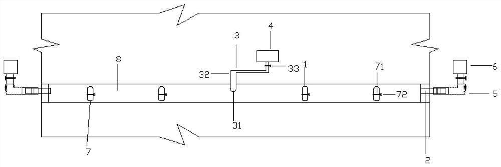
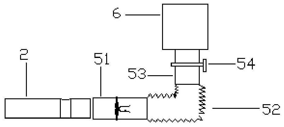
[0024] Figure 1-Figure 2 A prefabricated building structure vacuum grouting device is shown, the prefabricated building structure vacuum grouting device includes a grout inlet pipe 1, a grout outlet pipe 2, and a mixing drum sealingly connected to one end of the grout inlet pipe 1 through a grout inlet structure 3 4. An auxiliary structure 7 sealedly connected to one end of the pulp inlet pipe 1, a vacuum pump 6 sealed to one end of the pulp outlet pipe 2 through a slurry outlet structure 5,

[0025] The grout inlet pipe 1 communicates with the grout outlet pipe 2 through the hollow cavity 8 to be grouted, the mixing drum 4 is connected to the grout inlet pipe 1 at the center, and the auxiliary structure 7 is connected to the other inlet pipes. The slurry pipe 1 is connected.

[0026] The pulp feeding structure 3 includes a soft pulp feeding pipe 31, a pulp feeding connecting pipe 32 sealingly connected to one end of the soft pulp feeding pipe 31, and a pulp feeding valve 33...


PUM


Abstract

The invention discloses a prefabricated building structure vacuum grouting device which comprises a slurry inlet pipe, a slurry outlet pipe, a stirring barrel in sealed connection with one end of the slurry inlet pipe through a slurry inlet structure, an auxiliary structure in sealed connection with one end of the slurry inlet pipe, and a vacuum pump in sealed connection with one end of the slurry outlet pipe through a slurry outlet structure. The slurry inlet pipe is communicated with the slurry outlet pipe through a hollow cavity to be grouted; the stirring barrel is connected with the slurry inlet pipe in the center; and the auxiliary structure is connected with other slurry inlet pipes. A construction method includes the steps that the hollow cavity is formed, and all structures are connected; the hollow cavity is vacuumized, grouting is conducted until the situation that slurry flows out of the slurry outlet structure is observed, and a slurry outlet valve, the vacuum pump and a slurry inlet valve are closed; and grouting is completed after cleaning. According to the prefabricated building structure vacuum grouting device, vacuum grouting is adopted, the blocking condition in the grouting operation can be reduced, the accidental blocking condition can be reduced, the slurry inlet pipes at other positions can be replaced for slurry inlet, and the situation that grouting is conducted smoothly is guaranteed; and the sealing connection mode is simple and rapid, and the working efficiency is improved.

Description

technical field [0001] The invention relates to the technical field of building grouting, in particular to a prefabricated building structure vacuum grouting device and a construction method thereof. Background technique [0002] As the country vigorously promotes the pace of prefabricated buildings, prefabricated concrete structures such as prefabricated integral shear wall structures and prefabricated integral frame structures have been widely used in China, so the application of prefabricated concrete structures in prefabricated building structures account for a larger proportion. The connection method between the components in the prefabricated concrete structure mostly adopts the method of steel grouting connection, the steel grouting space is connected through a hollow cavity, and the grouting of multiple grouting spaces can be realized by grouting one of the grouting holes, completing two Connection of concrete structures. [0003] Due to the high viscosity of the g...

Claims


Application Information

Patent Timeline
Patent Type & Authority Applications(China)
IPC IPC(8): E04G21/12
CPCE04G21/12E04G21/122
Inventor 侯金林
Owner 侯金林
Why Eureka
Try Eureka