Pneumatic rotary drilling percussion drill for super-hard rock

A percussion drilling rig, superhard technology, applied in the direction of earthwork drilling, drilling equipment, drilling equipment and methods, etc., can solve the problems of poor practicality, high energy consumption, poor aerodynamic impact effect of drilling rigs, etc., and achieve easy movement and convenient use Effect

Active Publication Date: 2021-06-18
无锡安丰基础工程有限公司
View PDF6 Cites 0 Cited by
  • Summary
  • Abstract
  • Description
  • Claims
  • Application Information

AI Technical Summary

Problems solved by technology

[0003] At present, most of the existing superhard rock pneumatic rotary drilling percussion drilling rigs on the market have the following deficiencies in the process of use: when drilling with rotary drilling rigs, the existing drilling rigs have poor pneumatic impact effects, The digging process often requires greater energy consumption and poor practicability
In summary, most of the existing superhard rock pneumatic rotary percussion drilling rigs cannot meet the actual needs well

Method used


Image

  • Pneumatic rotary drilling percussion drill for super-hard rock
  • Pneumatic rotary drilling percussion drill for super-hard rock
  • Pneumatic rotary drilling percussion drill for super-hard rock

Examples


Embodiment 1

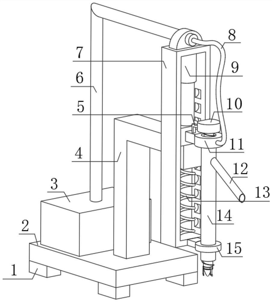
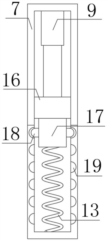
[0024] refer to Figure 1-3 , a pneumatic rotary drilling percussion drilling rig for superhard rock, comprising a base plate 2, a support rod 4 is fixedly connected to one side of the top outer wall of the base plate 2, a main body frame 7 is fixedly connected to one side outer wall of the support rod 4, and one part of the main body frame 7 An adjustment groove is provided on the side outer wall, and the top inner wall of the adjustment groove is fixedly connected with a cylinder 9, and one end of the piston rod of the cylinder 9 is fixedly connected with a slider 16, and the slider 16 is slidably connected on the inner wall of the adjustment groove, and the two sides of the adjustment groove Fitting grooves 19 distributed equidistantly are arranged on the side inner walls, pads 17 are provided on the outer wall of the bottom of the slider 16, and adapter blocks 18 are arranged on the outer walls of both sides of the pads 17. The outer wall of the opposite side is fixedly co...

Embodiment 2

[0032] refer to Figure 4 , a pneumatic rotary drilling percussion drilling machine for superhard rock. Compared with Embodiment 1, this embodiment further includes a universal wheel 23, and the universal wheel 23 is fixedly connected to the bottom outer wall of the support pad 1.

[0033]Working principle: when in use, the set universal wheels 23 are located at the bottom of each support pad 1, which is more conducive to movement when excavating at different positions.


PUM


Abstract

The invention discloses a pneumatic rotary drilling percussion drill for super-hard rock. The pneumatic rotary drilling percussion drill comprises a bottom plate, wherein one side of the outer wall of the top of the bottom plate is fixedly connected with a supporting rod; the outer wall of one side of the supporting rod is fixedly connected with a main body frame; an adjusting groove is formed in the outer wall of one side of the main body frame; the inner wall of the top of the adjusting groove is fixedly connected with an air cylinder; one end of a piston rod of the air cylinder is fixedly connected with a sliding block; the sliding block is in sliding connection with the inner wall of the adjusting groove; adaptive grooves, which are distributed at equal distances, are formed in the inner walls of two sides of the adjusting groove; a cushion block is arranged on the outer wall of the bottom of the sliding block; adaptive blocks are arranged on the outer walls of two sides of the cushion block; and the outer walls of opposite sides of the adaptive blocks are fixedly connected with the same extrusion spring. According to the pneumatic rotary drilling percussion drill disclosed by the invention, when the sliding block and the cushion block descend, the two adaptive blocks connected with the extrusion spring continuously enter the different adaptive grooves to form a vibration effect with certain frequency, so that a drilling position is more efficiently impacted and rotary drilling is convenient to carry out.

Description

technical field [0001] The invention relates to the technical field of pneumatic drilling rigs, in particular to a pneumatic rotary drilling percussion drilling rig for superhard rock. Background technique [0002] A drilling rig is a complex set of machines, which consists of machines, units and mechanisms. A drilling rig is a mechanical device that drives a drilling tool to drill underground to obtain physical geological data during exploration or mineral resource development (including solid ore, liquid ore, gas ore, etc.). Also known as drilling machine. The main function is to drive the drilling tool to break the rock at the bottom of the hole, and to lower or lift the drilling tool in the hole. It can be used to drill cores, ore cores, cuttings, gaseous samples, liquid samples, etc., to ascertain the conditions of underground geology and mineral resources. The ring and the ring seat are connected by a pin shaft, the ring seat and the hook rod are welded into one bod...

Claims


Application Information

Patent Timeline
IPC IPC(8): E21B6/00E21B7/02E21B15/00
CPCE21B6/00E21B7/02E21B15/00
Inventor 秦广琦甄芹芹秦广菊甄长富秦超丁颜周
Owner 无锡安丰基础工程有限公司
Why Eureka
Try Eureka