Refrigerating box and humidity control method for refrigerating box

A technology for refrigerators and control valves, applied in the field of humidity control and refrigerators, which can solve the problems of low defrosting efficiency, uneven defrosting, and long defrosting time, so as to improve the efficiency of defrosting, avoid a large amount of frosting, Avoid the effect of temperature rise and change in the box

Active Publication Date: 2021-06-18
QINGDAO HAIER BIOMEDICAL CO LTD
View PDF6 Cites 2 Cited by
  • Summary
  • Abstract
  • Description
  • Claims
  • Application Information

AI Technical Summary

Problems solved by technology

[0009] In order to solve the problems of large amount of frosting, long defrosting time, uneven defrosting and low defrosting efficiency in the temperature and humidity dual-control refrigerators in the prior art, the present invention provides a new type of refrigerator, which is equipped with a first evaporator and The second evaporator is used alternately, which reduces the amount of frost on the evaporator and shortens the defrosting time, and the hot gas bypass defrosting method can evenly heat the evaporator, which improves the defrosting efficiency and reduces the defrosting time. The effect of the generated heat on the temperature inside the box ensures the performance of the entire refrigerator

Method used


Image

  • Refrigerating box and humidity control method for refrigerating box
  • Refrigerating box and humidity control method for refrigerating box
  • Refrigerating box and humidity control method for refrigerating box

Examples


Embodiment 1

[0078] The present invention provides an embodiment of a refrigerated box, comprising: a box body:

[0079] The humidity detection element is arranged in the box. In some embodiments, the humidity detection element is a humidity sensor, which can be arranged inside the box during setting to detect the humidity value inside the box to ensure real-time Real-time detection of the humidity inside the box.

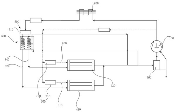
[0080] The refrigeration cycle is formed by connecting a compressor 100 , a condenser 200 , a throttle member 300 , an evaporator 400 , and a gas-liquid separator 500 . The evaporator 400 includes: a first evaporator 410 and a second evaporator 420 connected in parallel between the condenser 200 and the gas-liquid separator 500;

[0081] The first control valve assembly 500 is connected to the refrigeration cycle to control the first evaporator 410 and the second evaporator 420 to operate alternately, that is, through the action of the first control valve assembly 500, the fir...

Embodiment 2

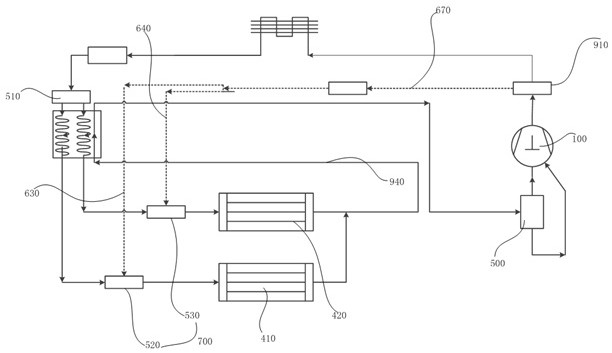
[0129] The present invention provides an embodiment of a refrigerating box, including a box body: a humidity detection element, which is arranged in the box body; The liquid separator 500 is connected to form;

[0130] A fan assembly for sucking the airflow in the box to the evaporator 400 and sending out the airflow passing through the evaporator 400; the evaporator 400 includes: connected in parallel between the condenser 200 and the gas-liquid separator 500 The first evaporator 410 and the second evaporator 420.

[0131] The first control valve assembly 500 is connected to the refrigeration cycle circuit to control the first evaporator 410 and the second evaporator 420 to operate alternately.

[0132] Compared with the first embodiment, the first control valve assembly 500 further includes a second solenoid valve 520 and a third solenoid valve 530 .

[0133] That is, in this embodiment, the first control valve assembly 500 includes: a first solenoid valve 510 , a second s...

Embodiment 3

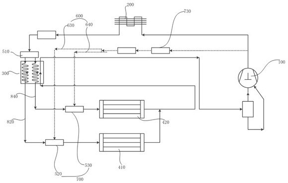
[0160] The present invention provides an embodiment of a refrigerated box, including a box body:

[0161] a humidity detection element, arranged in the box;

[0162] The refrigeration cycle is composed of the compressor 100, the condenser 200, the throttling component 300, the evaporator 400, and the gas-liquid separator 500 connected together;

[0163] a fan assembly for sucking the airflow in the box to the evaporator 400 and sending out the airflow passing through the evaporator 400;

[0164] The evaporator 400 includes a first evaporator 410 and a second evaporator 420 connected in parallel between the condenser 200 and the gas-liquid separator 500;

[0165] a first control valve assembly 500, connected to the refrigeration cycle circuit, for controlling the first evaporator 410 and the second evaporator 420 to operate alternately;

[0166] The bypass defrosting passage 600 is connected between the gas-liquid separator 500 and the gas outlet side of the compressor 100, s...


PUM


Abstract

The invention discloses a refrigerating box and a humidity control method for the refrigerating box. The refrigerating box comprises a box body, a humidity detection element arranged in the box body, a refrigeration circulation loop, a draught fan assembly, a first evaporator, a second evaporator, a first control valve assembly, a bypass defrosting channel, a second control valve assembly and a controller. The first evaporator and the second evaporator are connected in parallel. The first control valve assembly is connected to the refrigeration circulation loop and used for controlling the first evaporator and the second evaporator to operate alternately. The bypass defrosting channel is connected between a gas-liquid separator and the gas outlet side of a compressor and used for enabling a refrigerant flowing out of the gas outlet side of the compressor to flow through the first evaporator and the second evaporator or sequentially flow through the first evaporator and the second evaporator. The second control valve assembly is used for controlling the on-off of the bypass defrosting channel. The controller is in communication connection with the humidity detection element, the first control valve assembly and the second control valve assembly. According to the refrigerating box and the humidity control method for the refrigerating box, the problems that in the prior art, a temperature and humidity double-control refrigerating box is large in frosting amount, long in defrosting time, uneven in defrosting and low in defrosting efficiency are solved.

Description

technical field [0001] The invention relates to the technical field of medical refrigeration equipment, in particular to a refrigerator and a humidity control method for the refrigerator. Background technique [0002] Air-cooled small refrigeration equipment generally uses a finned evaporator installed in the inner space of the box, and is equipped with a fan and an air duct. Under the action of the fan, the air in the box circulates through the evaporator, and then the evaporator refrigerates the air flowing through the evaporator. [0003] In such products, because the surface temperature of the evaporator is very low, during the air circulation process in the box, the water vapor in the air will be precipitated on the surface of the evaporator below the air dew point temperature and form frost on the surface of the evaporator. or ice. When the surface of the evaporator is covered with frost or ice, the evaporator loses the cooling capacity of the air flowing through the...

Claims


Application Information

Patent Timeline
Patent Type & Authority Applications(China)
IPC IPC(8): F25D11/00F25D17/04F25D21/06F25B47/02
CPCF25D11/00F25D17/045F25D21/06F25B47/022F25D2317/04111F25D2600/06F25B2347/02
Inventor 冷川杨民灵李方煜陈君牛愉涛杨波
Owner QINGDAO HAIER BIOMEDICAL CO LTD
Why Eureka
Try Eureka