Multistage finned tube capable of restraining frost formation and intensifying natural convection

A technology of natural convection and finned tubes, which is applied in the direction of tubular elements, lighting and heating equipment, heat exchange equipment, etc., can solve the problem of poor heat exchange performance of LNG air-temperature vaporizer, large influence of air-temperature vaporizer, Problems such as low outlet temperature of the gasifier, to achieve the effect of improving distribution uniformity, small influence, and large natural convection heat transfer

Active Publication Date: 2015-11-25
XI AN JIAOTONG UNIV
View PDF8 Cites 3 Cited by
  • Summary
  • Abstract
  • Description
  • Claims
  • Application Information

AI Technical Summary

Problems solved by technology

This is because: (1) The overall heat transfer performance of the existing LNG air-temperature gasifier is poor, the equipment occupies a large area, is heavy, and has a large initial investment, making this type of gasifier generally used for gasification Small gasification station, less used in LNG receiving terminal
(2) The air-temperature gasifier is greatly affected by the external environment
In the winter in northern China, the air-heated gasifier is seriously frosted, resulting in the outlet temperature of the gasifier being too low, which cannot meet the needs of use
(3) After the air-temperature gasifier has been running for a period of time, it is necessary to use the spare gasifier to shut down and defrost, which increases the operating cost of the equipment

Method used


Image

  • Multistage finned tube capable of restraining frost formation and intensifying natural convection
  • Multistage finned tube capable of restraining frost formation and intensifying natural convection
  • Multistage finned tube capable of restraining frost formation and intensifying natural convection

Examples


Embodiment Construction

[0025] The present invention will be described in detail below in conjunction with the accompanying drawings and embodiments.

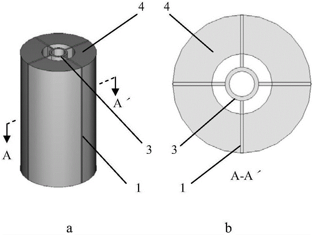
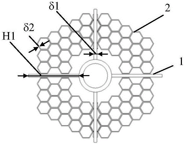
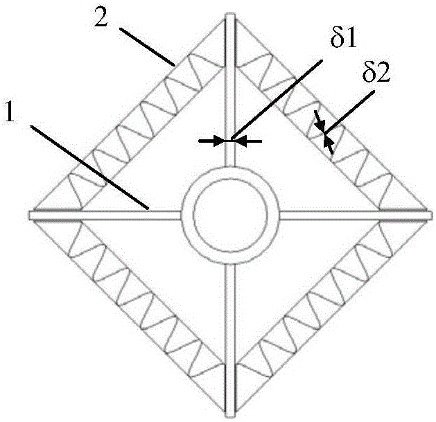
[0026] Such as figure 1 As shown, the multi-stage finned tube for suppressing frosting and enhancing natural convection of the present invention includes a central tube 3, a plurality of star-shaped primary fins 1 drawn from the surface of the central tube 3 and a connecting primary fin 1 The secondary fins 2 of the fins (both the primary fins and the secondary fins are longitudinal fins, the so-called longitudinal fins are parallel to the axis of the central tube), and the secondary fins 2 are closely connected with the primary fins 1 . All secondary fins 2 maintain a certain distance L1 from the central tube 3 . As a preferred embodiment of the present invention, said L1>10mm. The secondary fin 2 has a honeycomb structure ( Figure 2a ), corrugated fin structure ( Figure 2b ), grid fin structure ( Figure 2c ) or curved fin structure ( Figur...


PUM


Abstract

The invention discloses a multistage finned tube capable of restraining frost formation and intensifying natural convection. The multistage finned tube comprises a central tube, a plurality of primary longitudinal fins which are distributed in a star manner and secondary fins connected with the primary longitudinal fins. The surfaces of the secondary fins are parallel to the axis of the central tube, and the outer space of the central tube is divided into a plurality of longitudinal parallel channels by the secondary fins. The finned tube can form a sealed air flow channel through the primary fins and the secondary fins. The secondary fins of the finned tube can prevent steam in air from being conveyed to the roots of the fins from the outer space of the finned tube, the steam can only enter from the top space of the finned tube, and the frost formation is restrained. The large specific surface area of the secondary fins enlarges the distribution area of frost, improves the frost distribution evenness, prevents frost from piling at the root of the central tube and the roots of the primary fins, enables the frost thickness on the surfaces of the fins to become thin, reduces the heat transfer resistance and quickens the defrosting speed. By means of the large specific surface area of the secondary fins, the heat exchange area on the air side is enlarged, and heat exchange is intensified.

Description

technical field [0001] The invention belongs to the technical field of heat exchangers, in particular to an air-temperature vaporizer for vaporizing low-temperature fluids such as liquefied natural gas, liquid oxygen, and liquid nitrogen. Background technique [0002] As the cleanest fossil energy, natural gas has gradually increased its proportion in the world's energy structure. Natural gas is stored and transported in the form of liquefied natural gas (LNG), which has the advantages of low cost, convenient use, safety and reliability. The LNG industry will become a key industry in China's future energy development. In recent years, my country's LNG industry has developed rapidly, and the number of domestic LNG receiving stations and gasification stations has increased rapidly. [0003] In practical application, the liquefied natural gas needs to be vaporized and brought to normal temperature before it can be used. The gasifier is the core equipment of the gasification ...

Claims


Application Information

Patent Timeline
Patent Type & Authority Applications(China)
IPC IPC(8): F28F1/20F28F21/08
Inventor 闫孝红
Owner XI AN JIAOTONG UNIV
Why Eureka
Try Eureka