Mobile intelligent low-power-consumption electric energy meter capable of being used in extreme environment
A smart electric energy meter and extreme environment technology, applied in the field of electric energy meter, can solve the problems such as unusable, achieve cost saving, reasonable structure, and solve the effect of difficult electricity charge recovery
- Summary
- Abstract
- Description
- Claims
- Application Information
AI Technical Summary
Problems solved by technology
Method used
Image

Examples
Embodiment 1
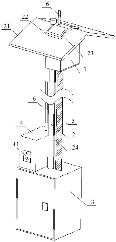
[0036] Such as figure 1 As shown, a mobile intelligent low-power energy meter that can be used in extreme environments includes a box 1 for storing the smart energy meter 11, a column 2 for supporting the box 1, and a lifter for lifting the box 1. Mechanism 3 and power consumption mechanism 4 for users to take electricity.
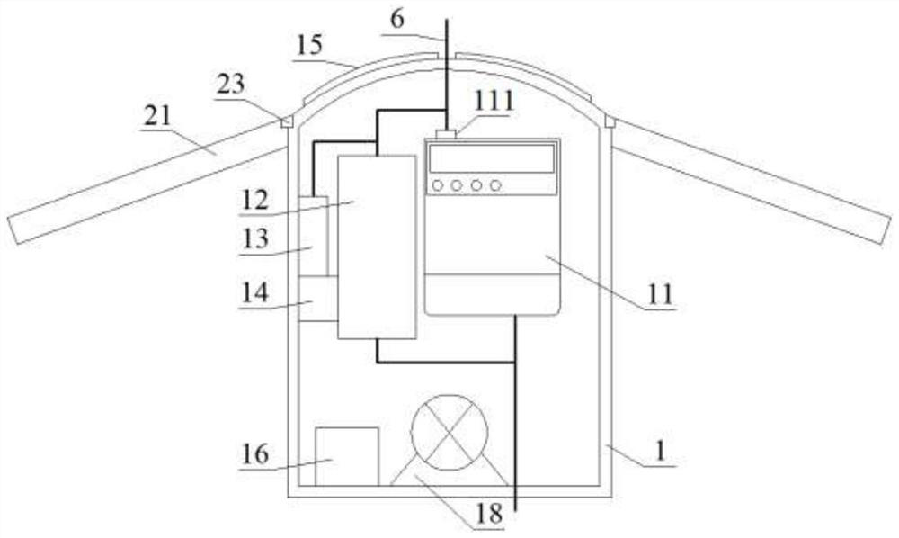
[0037] Such as figure 2 As shown, the upper part of the smart energy meter 11 is connected to the incoming line terminal through the manual switch 111 provided, the lower part of the smart energy meter 11 is provided with the outgoing line terminal, and a relay 12 is provided on one side of the box. The relay 12 is a commercially available GN-24VDC-1A -16 relays, a power converter 13 is provided on one side of the relay 12, and the power converter 13 is a commercially available YK-DD12S24X power converter, and an electromagnetic lock 14 is provided under the power converter 13, and the electromagnetic lock 14 is a commercially available DSN-BMY electroma...
Embodiment 2
[0051] This embodiment is basically the same as Embodiment 1, the difference is that the working mode of the smart energy meter 1 is different:
[0052] First, the user connects the equipment that needs electricity to the electrical socket 41, and completes the online payment by scanning the QR code above the electrical socket 41. Then, the electrical socket 41 is powered on and started to operate. One end of the coil of the relay 12 is connected to the smart electric energy The outlet end of the meter 11, the other end is connected to the neutral line, one end of the moving contact of the relay 12 is connected to the incoming line end of the smart energy meter 11, the other end is connected to the positive input end of the power converter 13, and the negative input end of the power converter 13 is connected to Zero line, the positive output end of the power converter 13 is connected to one end of the electromagnetic lock 14, the negative output end of the power converter 13 is...
Embodiment 3
[0054] This embodiment is basically the same as Embodiment 1, except that the dimensions of the drive chain 5 are different:
[0055] Such as Figure 6 , 7 As shown, transmission chain 5 is connected by several transmission blocks 51, and each transmission block 51 is long 25cm, high 9cm, wide 6cm, and transmission block 51 is by the clamp block 52 that is positioned at both sides and is positioned at the middle and is used for connecting two groups The connecting rod 53 of the clamping block 52 is formed. The top of the clamping block 52 is provided with a bump 54, and the bottom of the clamping block 52 is provided with a groove 55. A through hole 56 is provided, and an elastic rope 57 is provided through the through hole 56. The elastic rope 57 runs through and connects each group of clamping blocks 52 in turn, and the middle part of the connecting rod 53 is provided with a strip groove 58. The spacing between the grooves 58 is the same as the width of the bar-shaped prot...
PUM
 Abstract
Description
Claims
Application Information
 - R&D Engineer
- R&D Manager
- IP Professional
- Industry Leading Data Capabilities
- Powerful AI technology
- Patent DNA Extraction
Browse by: Latest US Patents, China's latest patents, Technical Efficacy Thesaurus, Application Domain, Technology Topic.
© 2024 PatSnap. All rights reserved.Legal|Privacy policy|Modern Slavery Act Transparency Statement|Sitemap