Distribution transformer

A distribution transformer and transformer oil tank technology, applied in the field of transformers, can solve the problems of low efficiency of distribution transformers, large size of distribution transformers, inconvenient installation and transportation, etc., to improve power supply efficiency, increase automatic compensation function, and save space Effect

Inactive Publication Date: 2021-06-18
李龙波
View PDF0 Cites 0 Cited by
  • Summary
  • Abstract
  • Description
  • Claims
  • Application Information

AI Technical Summary

Problems solved by technology

[0002] At this stage, the use efficiency of distribution transformers is low, and the conversion efficiency is very low. The power factor of distribution transformers used in rural power grids is generally low, and the quality of power supply is poor. With the continuous improvement of people's lives, the power load continues to increase. , so that the whole load is obviously inductive, so the power factor is low, and now the average power factor in rural areas is around 0.7
Moreover, the existing distribution transformers are large in size and weight, waste materials, waste space, and are not easy to install and transport

Method used


Image

  • Distribution transformer
  • Distribution transformer
  • Distribution transformer

Examples


Embodiment Construction

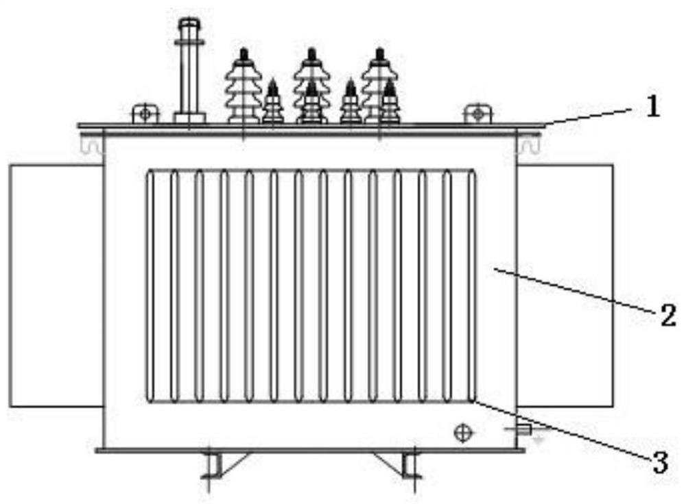
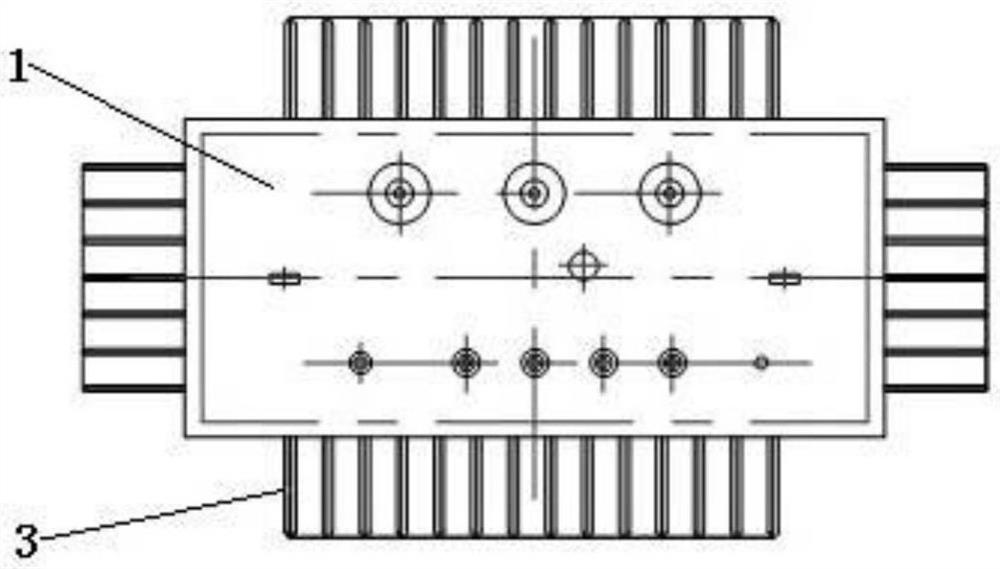
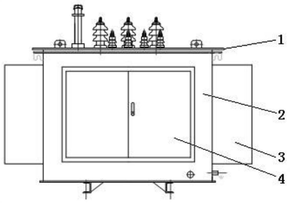
[0009] Accompanying drawing is a kind of specific embodiment of the present invention.

[0010] In the distribution transformer of the present invention, an automatic compensation control box 4 is fixed on the outer surface of the transformer oil tank, and a computer automatic compensation controller, a three-phase knife switch and several capacitors are installed in the automatic compensation control box, and a mutual inductor is installed inside the transformer oil tank; The automatic compensation controller is connected to the low-voltage three-phase circuit of the transformer through the three-phase knife switch, and the computer automatic compensation controller is also connected to the low-voltage three-phase circuit through several capacitors, and each capacitor is connected to the low-voltage three-phase circuit at the same time, and the computer automatically compensates The controller is also connected to the transformer, which is installed on the lead terminal of one...


PUM


Abstract

The invention belongs to transformers, and relates to a distribution transformer. An automatic compensation control box is fixed on the outer surface of a transformer oil tank; a computer automatic compensation controller, a three-phase knife switch and a plurality of capacitors are mounted in the automatic compensation control box; and a mutual inductor is mounted in the transformer oil tank; the computer automatic compensation controller is connected with a low-voltage three-phase circuit of the transformer through the three-phase knife switch; the computer automatic compensation controller is also connected with the low-voltage three-phase circuit through a plurality of capacitors; each capacitor is simultaneously connected with the low-voltage three-phase circuit; the computer automatic compensation controller is also connected with the mutual inductor; and the mutual inductor is arranged on a lead terminal of one phase of the low-voltage three-phase circuit. The beneficial effects of the invention are that the automatic compensation function is added, the power supply efficiency is improved, the power factor can be automatically improved, the power supply quality is improved, the size is small, the weight is light, raw materials are saved, the installation is simple, the equipment transportation is convenient, and the space is saved.

Description

technical field [0001] The invention belongs to transformers, and relates to a power distribution transformer. Background technique [0002] At this stage, the use efficiency of distribution transformers is low, and the conversion efficiency is very low. The power factor of distribution transformers used in rural power grids is generally low, and the quality of power supply is poor. With the continuous improvement of people's lives, the power load continues to increase. , so that the entire load is obviously inductive, so the power factor is low, and the average power factor in rural areas is now around 0.7. Moreover, the existing distribution transformer has a large volume and a large weight, wastes materials, wastes space, and is inconvenient for installation and transportation. Contents of the invention [0003] In order to make up for the deficiencies of the prior art, the present invention provides a distribution transformer with high power supply efficiency, good po...

Claims


Application Information

Patent Timeline
Patent Type & Authority Applications(China)
IPC IPC(8): H01F27/40H01F27/42H02J3/18
CPCH01F27/40H01F27/42H02J3/1864Y02E40/30
Inventor 李龙波
Owner 李龙波
Why Eureka
Try Eureka