
A sierpinski-like fractal ultra-wideband antenna and its design method

A technology of an ultra-wideband antenna and a design method, applied in the field of wireless communication, can solve the problems of large physical size and difficult integration of ultra-wideband antennas, and achieve the effects of light weight, good directivity and low loss

Active Publication Date: 2022-02-22
TIANJIN UNIV
View PDF3 Cites 0 Cited by
  • Summary
  • Abstract
  • Description
  • Claims
  • Application Information

AI Technical Summary

Problems solved by technology

[0005] However, the physical size of current UWB antennas is large and not easy to integrate. Therefore, there is an urgent need for UWB antennas that can solve the above technical problems in design.

Method used


Image

  • A sierpinski-like fractal ultra-wideband antenna and its design method
  • A sierpinski-like fractal ultra-wideband antenna and its design method
  • A sierpinski-like fractal ultra-wideband antenna and its design method

Examples


Embodiment 1

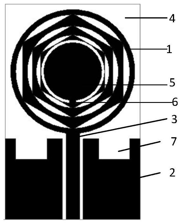
[0051] like figure 1 As shown, the class Sierpinski fractal ultra-wideband antenna of the present invention comprises a dielectric substrate 4, and one side of the dielectric substrate 4 is pasted with a radiation element 1, a feed element 3 and a ground element 2 (radiation element 1, feed element 3 The ground unit 2 is arranged on the same surface of the dielectric substrate 4 to form a coplanar waveguide structure, which has lower loss compared to the existing microstrip line feed, and is more beneficial to integration with other circuit structures);

[0052] The radiation unit 1 is a fractal patch formed by 3 iterations of fractal, a first sub-patch 5, and a second sub-patch 6, and is a connected shaped patch, and an etching slit is formed on the shaped patch .

[0053] Further, the fractal patch is a 3rd-order structure of the Sierpinski fractal structure, the 1st-order structure is formed by nesting a ring and a regular hexagon with the middle circle removed, and the 2nd-...

Embodiment 2

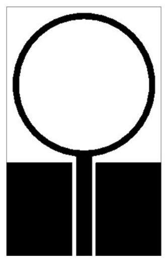
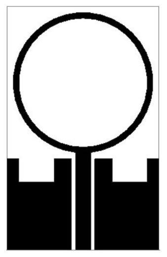
[0063] On the basis of embodiment 1, as shown in Figure 2, the design method of class Sierpinski fractal ultra-wideband antenna of the present invention comprises the following steps:

[0064] (1) Using the Sierpinski fractal method, the radiation unit 1 is fractalized three times to obtain a fractal patch, which is combined with the first sub-patch 5 and the second sub-patch 6 on the fractal patch to form a connected body patch;

[0065] (1-1) Embed a regular hexagon in the ring as the initial structure, cut a circle in the middle of the regular hexagon so that the middle of the regular hexagon has a hollow circle, thus forming the first iterative structure; wherein, the initial structure The radius of the outer circle of the ring is 6mm, the radius of the inner circle is 5.5mm, and the radius of the circle cut in the middle of the regular hexagon is 4.8mm;

[0066] (1-2) Reduce the first iterative structure to obtain the first scaling structure, and fill the first scaling s...


PUM


Abstract

The invention discloses a Sierpinski-like fractal ultra-wideband antenna, which includes a dielectric substrate, and a radiation unit, a feeding unit and a grounding unit are pasted on one side of the dielectric substrate; the radiation unit is a fractal patch formed by at least three iterations of fractal, the first The sub-patch and the second sub-patch are connected shaped patches, and etching slits are formed on the shaped patches; the feeding unit is connected to the bottom of the radiation unit; the center of the top edge of the grounding unit forms a rectangular concave The slot and the grounding unit are arranged symmetrically on both sides of the feeding unit. The antenna forms a fractal structure after 3 iterations. Through the nesting of the ring and the regular hexagon, the current distribution on the radiation patch is not limited to the edge of the ring. By cutting the middle circle of the regular hexagon and performing multiple fractal The iteration of the structure greatly increases the propagation path of the surface current of the radiating patch, effectively reduces the resonant frequency, and thus reduces the physical size of the antenna.

Description

technical field [0001] The invention belongs to the field of wireless communication, and in particular relates to a Sierpinski-like fractal ultra-wideband antenna and a design method thereof. Background technique [0002] Ultra-Wideband technology (Ultra-Wideband, UWB) is a wireless carrier communication technology. It does not use a sinusoidal carrier, but uses nanosecond-level non-sinusoidal narrow pulses to transmit data. It occupies a wide range of spectrum, in 3.1 The -10.6GHz frequency band occupies more than 500MHz of bandwidth. UWB technology has advantages such as low equipment power consumption, safe transmission, strong anti-interference ability, and strong multipath resolution ability, which makes UWB technology attract more and more researchers' interest in the fields of radio frequency, circuit, system and antenna design. [0003] Compared with other traditional wireless communication technologies (such as RFID, WIFI, etc.), UWB is a new type of carrier-free w...

Claims


Application Information

Patent Timeline
Patent Type & Authority Patents(China)
IPC IPC(8): H01Q1/38H01Q1/48H01Q1/50H01Q5/25H01Q9/04
CPCH01Q1/38H01Q1/48H01Q1/50H01Q5/25H01Q9/0464
Inventor 邹强姜时雨
Owner TIANJIN UNIV
Learn More