Driving device

A technology for driving devices and brakes, applied in the directions of electromechanical devices, electric components, casings/covers/supports, etc., can solve problems such as sliding resistance loss and loss, and achieve the effect of suppressing loss increase

Pending Publication Date: 2021-06-18
SUMITOMO HEAVY IND LTD
View PDF1 Cites 0 Cited by
  • Summary
  • Abstract
  • Description
  • Claims
  • Application Information

AI Technical Summary

Problems solved by technology

[0005] If a shielding wall is provided to prevent the intrusion of dust from the brake housing space to other housing spaces like the above-mentioned drive unit, there will be a problem of loss of sliding resistance at the contact portion between the shielding wall and the rotating shaft.
Moreover, if an electrically driven mechanism is provided instead of the shielding wall, there will be a problem of loss due to its driving.

Method used


Image

  • Driving device
  • Driving device
  • Driving device

Examples


Deformed example 1

[0072] Figure 5 It is a figure which shows the modification 1 of a 1st barrier wall. Figure 5 The first barrier wall 31 of Modification 1 on a cross section passing through the central axis O1 is shown in . like Figure 5 As shown, the first barrier wall 31 may have a structure including a first fixed wall 31C supported on the housing 11 side and a first rotating wall 31D supported on the rotor shaft 13 side.

[0073] The first fixed wall 31C has a disk portion 31C1 extending radially and circumferentially, and a plurality of protruding portions 31C2 and 31C3 axially protruding from the center of the disk portion 31C1 to form a gap G3. The first rotating wall 31D has a disk portion 31D1 extending radially and circumferentially, and a plurality of protruding portions 31D2 to 31D4 axially protruding from the middle and outer peripheral ends of the disk portion 31D1 to form a gap G3. The protrusions 31C2 and 31C3 correspond to an example of the first fixed-side protrusions a...

Deformed example 2

[0078] Figure 6 It is a figure which shows the modification 2 of a 1st barrier wall. Figure 6 The first barrier wall 31 of Modification 2 on a cross section passing through the central axis O1 is shown in . like Figure 6 As shown, the first blocking wall 31 may have a structure including a first fixed wall 31E supported on the housing 11 side and a first rotating wall 31F supported on the rotor shaft 13 side. In addition to having a gap G4 between the first fixed wall 31E and the first rotating wall 31F, the first barrier wall 31 is further provided with an foreign matter storage portion H1 for storing foreign matter in the first fixed wall 31E. The foreign matter storage part H1 has an opening X1 in the brake storage space W2, but does not have an opening in the detection part storage space W1. When the foreign matter storage part H1 is seen through from the opening part X1 side, the opening part X1 is smaller than the foreign matter storage part H1. On the inlet side ...


PUM


Abstract

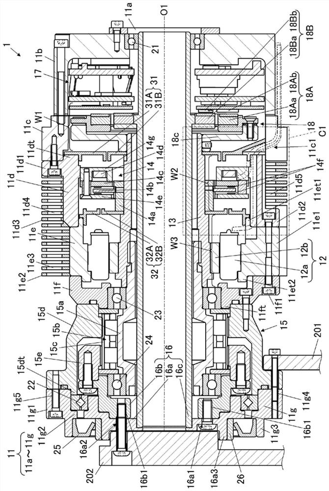
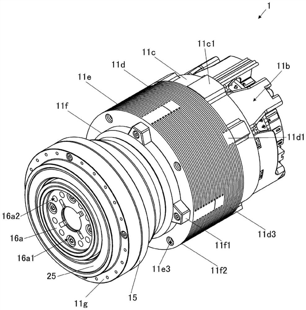
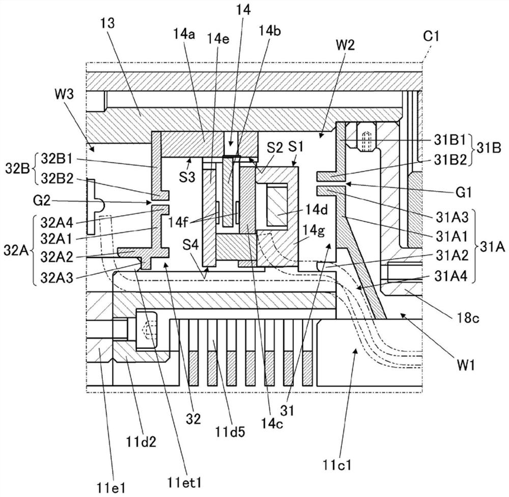
The invention provides a driving device capable of suppressing the circulation of a foreign matter from a brake storage space to another storage space while suppressing an increase in loss. The driving device (1) comprises a motor (12), a brake (14), a detecting part (18), a casing (11), and a rotary shaft part (13, 16c) which rotates relative to the casing. A brake housing space (W2) for housing the constituent members of the brake and a detecting part housing space (W1) for housing the constituent members of the detecting part communicate with each other. The driving device includes a first inhibition wall (31) which inhibits the circulation of a foreign matter between the brake housing space and the detecting part housing space, and the first inhibition wall (31) has a first fixing wall (31A) supported on the casing side and a first rotation wall (31B) supported on the rotation shaft part side, and a gap (G1) is provided between the first fixing wall and the first rotation wall.

Description

[0001] This application claims priority based on Japanese Patent Application No. 2019-225118 filed on December 13, 2019. The entire contents of this Japanese application are incorporated herein by reference. technical field [0002] The invention relates to a drive device. Background technique [0003] In Patent Document 1, as a background art, there is shown a drive device having a shield wall that prevents movement of dust between a brake housing space and an encoder housing space. Furthermore, Patent Document 1 discloses a drive device that does not include a shield wall, but instead includes a radial fan that flows air toward an optical encoder to prevent dust from adhering. [0004] Patent Document 1: Japanese Patent Application Laid-Open No. 10-225064 [0005] If a shielding wall is provided to prevent dust from intruding from the brake accommodating space to other accommodating spaces as in the above-mentioned driving device, there will be a problem of loss of slidi...

Claims


Application Information

Patent Timeline
Patent Type & Authority Applications(China)
IPC IPC(8): H02K11/21H02K11/215H02K11/22H02K7/116
CPCH02K7/116H02K11/21H02K11/215H02K11/22H02K5/10H02K7/1025H02K7/14
Inventor 深泽俊树
Owner SUMITOMO HEAVY IND LTD
Why Eureka
Try Eureka