Current source contactor drive with economizers

Active Publication Date: 2021-09-23
HAMILTON SUNDSTRAND CORP
View PDF0 Cites 0 Cited by
  • Summary
  • Abstract
  • Description
  • Claims
  • Application Information

AI Technical Summary

Benefits of technology

The patent describes a system and method for controlling a contactor using a current source control circuit and a delay circuit. The system includes a contact, a coil, a source of voltage, a pass element, a current source control circuit, and a close command line. The current source control circuit controls the opening and closing of the contactor by controlling the current in the coil. The delay circuit controls the opening and closing of the contactor by controlling the current in the pass element. The system can provide a first current to close the contactor and a second current to hold it closed. The second current is lower than the first current and is controlled by the current source control circuit. The system can also use a linear regulator or a bipolar junction transistor for the current source control. The technical effect of the system is to provide a reliable and efficient way to control the opening and closing of a contactor.

Problems solved by technology

The failure of the economizer can either cause the coil drive circuitry to trip on overcurrent and inadvertently de-energize the contactor, or may not be detectible if the pull-in current is below the overcurrent threshold.

Method used


Image

  • Current source contactor drive with economizers
  • Current source contactor drive with economizers
  • Current source contactor drive with economizers

Examples


Embodiment Construction

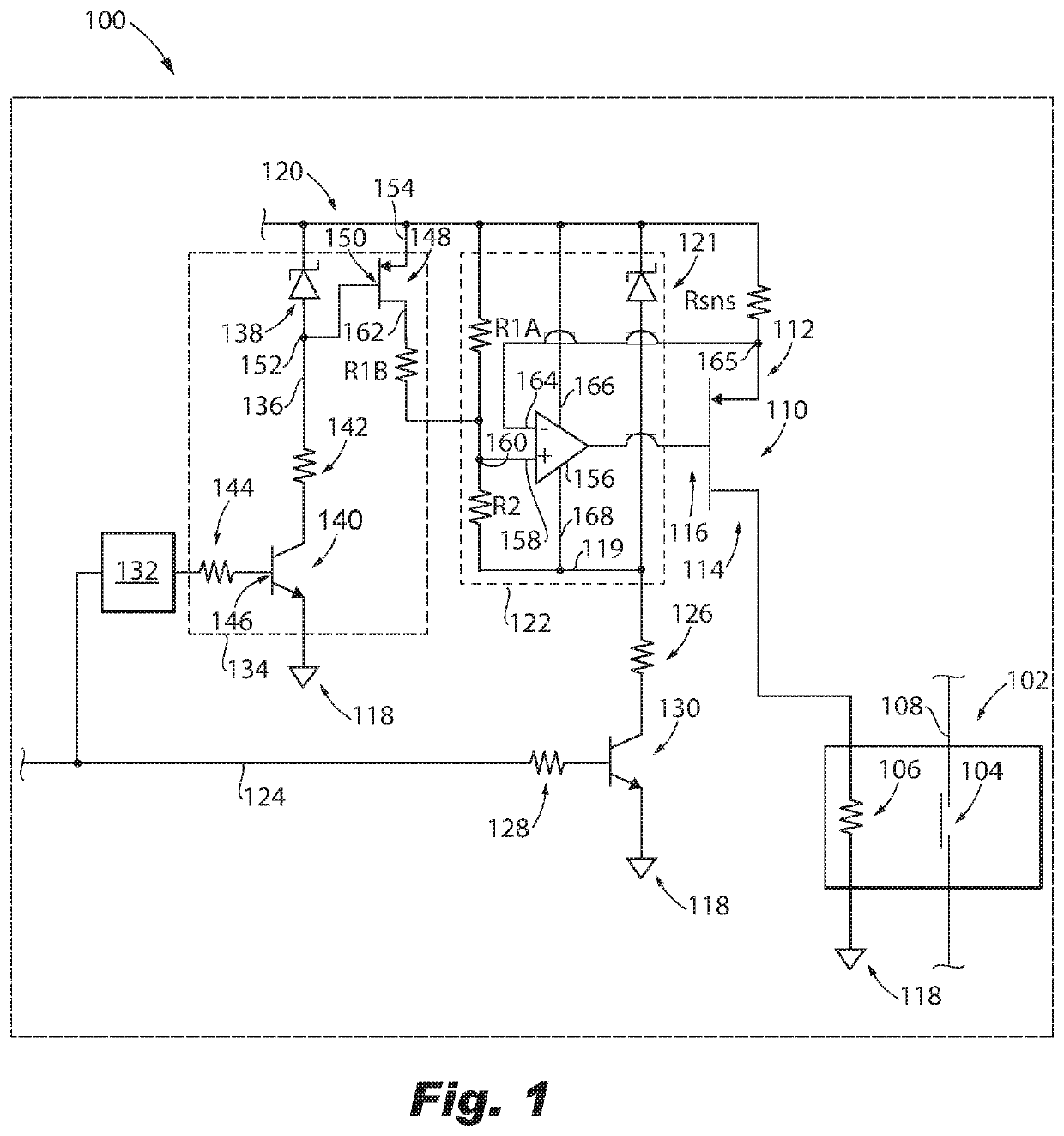
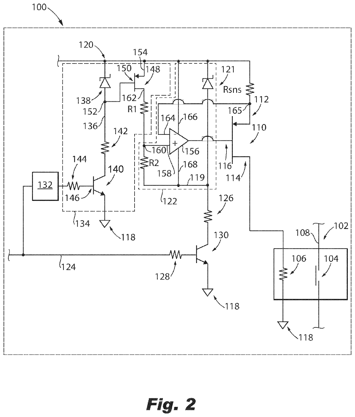
[0017]Reference will now be made to the drawings wherein like reference numerals identify similar structural features or aspects of the subject disclosure. For purposes of explanation and illustration, and not limitation, a partial view of an embodiment of a system in accordance with the disclosure is shown in FIG. 1 and is designated generally by reference character 100. Other embodiments of systems in accordance with the disclosure, or aspects thereof, are provided in FIGS. 2-3, as will be described. The systems and methods described herein can be used to improve economizer operations using a current source rather than an on / off switch to guarantee coil current, e.g., in aerospace applications.

[0018]The system 100 includes a contactor 102 that includes a contact 104 operatively connected to a coil 106 for actuating the contactor 102 to open and close a circuit 108. A pass element 110 includes a source 112, a drain 114, and a gate 116. The drain 114 is electrically connected to the...


PUM


Abstract

A system includes a contactor operatively connected to a coil for actuating the contactor to open and close a circuit. A pass element includes a source, a drain, and a gate, wherein the drain is electrically connected to the coil, and wherein the coil is in series between the pass element and ground. A voltage source is connected to the source of the pass element to pass current into the coil when the pass element is in a pass state. A current source control circuit with economizer is operatively connected to the gate of the pass element. A delay circuit is operatively connected to the current source control circuit with economizer and to a command line to command a lower current for holding the contactor closed after a delay has expired for the contactor to transition.

Description

BACKGROUND1. Field[0001]The present disclosure relates to power distribution systems, and more particularly to electrical power generation and distribution system (EPGDS) contactors such as used in aerospace applications.2. Description of Related Art[0002]Electrical power generation and distribution system (EPGDS) contactors often have built-in economizers which switch from a high current “pull-in” mode, to a lower current “hold” mode, for reduced power dissipation in the contactor coil and coil drive. The failure of the economizer can either cause the coil drive circuitry to trip on overcurrent and inadvertently de-energize the contactor, or may not be detectible if the pull-in current is below the overcurrent threshold.[0003]The conventional techniques have been considered satisfactory for their intended purpose. However, there is an ever present need for improved systems and methods for EPGDS contactors. This disclosure provides a solution for this need.SUMMARY[0004]A system incl...

Claims


Application Information

Patent Timeline
IPC IPC(8): H01H47/32H01H47/02H01H9/54
CPCH01H47/325H01H2009/544H01H9/542H01H47/02H01H47/32H01H2047/008
Inventor JOYCE, THOMAS P.VANEVENHOVEN, JORDAN K.FILIPSKI, NATALIE
Owner HAMILTON SUNDSTRAND CORP
Why Eureka
Try Eureka