MEMS device and process

Active Publication Date: 2021-05-13
CIRRUS LOGIC INC
View PDF0 Cites 0 Cited by
  • Summary
  • Abstract
  • Description
  • Claims
  • Application Information

AI Technical Summary

Benefits of technology

The patent is about a method of making a MEMS device by creating discontinuities on its surface. These discontinuities help to change the way liquid glue or bonding solution can flow on the surface of the device. This allows the device to be protected and separated from the liquid during the bonding process. The technical effect of this method is to improve the reliability and performance of the MEMS device by preventing damage to its vulnerable components during the bonding process.

Problems solved by technology

For example, it is known that bond wires within the MEMS package give rise to interference and may potentially cause a degradation in the RF and / or PSR performance of the transducer.
However, a problem that may be encountered with the flip-chip arrangement illustrated in FIG. 3 is that, during a process of adhering the top surface of the MEMS to the upper surface of the substrate, the bonding solution (e.g. glue or epoxy) may flow towards the transducer.
It will be appreciated that the presence of the bonding solution in the MEMS transducer e.g. within the acoustic cavities and / or in contact with the flexible membrane transducer, may undermine the performance of the transducer.

Method used


Image

  • MEMS device and process
  • MEMS device and process
  • MEMS device and process

Examples


Embodiment Construction

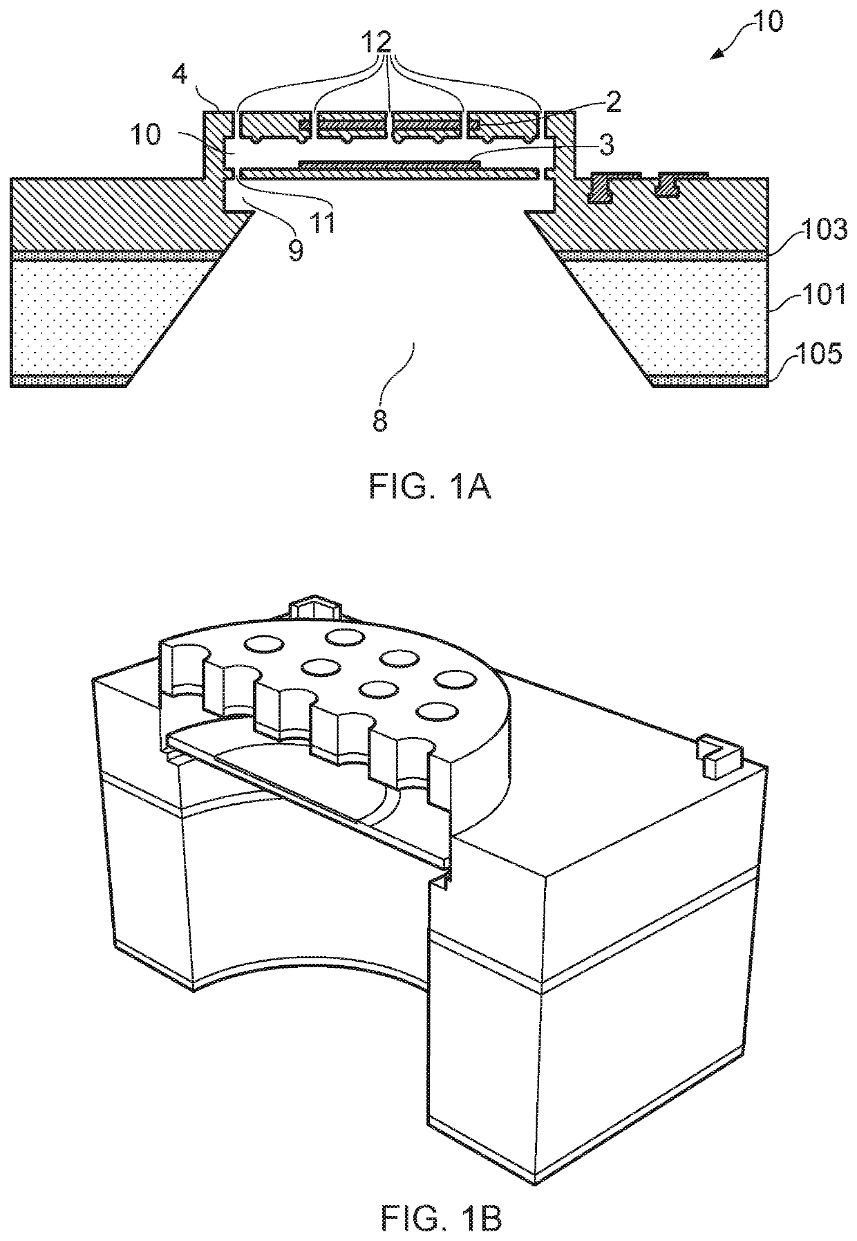
[0020]According to an example embodiment of a first aspect there is provided a MEMS device comprising a MEMS transducer, wherein the MEMS transducer comprises: a substrate having a cavity which forms a cavity opening in a upper surface of the substrate; a flexible membrane supported so as to overlie the cavity, wherein a top surface of the MEMs device comprises a barrier region, the barrier region being at least partially provided laterally outside a region which overlies the cavity opening in the upper surface of the substrate.

[0021]The barrier region may comprise one or more discontinuities in the surface of the MEMS device. Advantageously, the discontinuities serve to alter the epoxy wettability of the top surface of the MEMS device in the barrier region. Thus it is possible to define (die attach) wettable and non-wettable regions on the top surface of the MEMS device. Specifically, by providing one or more surface features or discontinuities it is possible to define epoxy non-we...


PUM

PropertyMeasurementUnit
Flow rateaaaaaaaaaa
Flexibilityaaaaaaaaaa
Wettabilityaaaaaaaaaa

Abstract

The present disclosure describes techniques for altering the epoxy wettability of a surface of a MEMS device. Particularly applicable to flip-chip bonding arrangements in which a top surface of a MEMS device is adhered to a package substrate. A barrier region is provided on a top surface of the MEMs device, laterally outside a region which forms, or overlies, the backplate and / or the cavity in the transducer substrate. The barrier region comprises a plurality of discontinuities, e.g. dimples, which inhibit the flow of epoxy.

Description

TECHNICAL FIELD[0001]This application relates to micro-electro-mechanical system (MEMS) devices and processes, and in particular to a MEMS device and process relating to a transducer, for example a capacitive microphone.BACKGROUND INFORMATION[0002]MEMS devices are becoming increasingly popular. MEMS transducers, and especially MEMS capacitive microphones, are increasingly being used in portable electronic devices such as mobile telephone and portable computing devices.[0003]Microphone devices formed using MEMS fabrication processes typically comprise one or more moveable membranes and a static backplate, with a respective electrode deposited on the membrane(s) and backplate, wherein one electrode is used for read-out / drive and the other is used for biasing. A substrate supports at least the membrane(s) and typically the backplate also. In the case of MEMS pressure sensors and microphones the read out is usually accomplished by measuring the capacitance between the membrane and backp...

Claims


Application Information

Patent Timeline
IPC IPC(8): H04R19/00B81B3/00B81C3/00H04R19/04
CPCH04R19/005B81B3/0021B81C3/001H04R19/04B81B2203/0353B81B2201/0257B81B2203/0315B81B2203/033B81B2203/0127H04R2201/003H04R31/006B81C1/00825B81C2203/037B81B7/0032B81C1/00261
Inventor PIECHOCINSKI, MAREK SEBASTIANBRIOSCHI, ROBERTOACHEHBOUNE, RKIA
Owner CIRRUS LOGIC INC
Why Eureka
Try Eureka